4.11 Rapid Aerodynamics: Body-Only
1. Import CAD
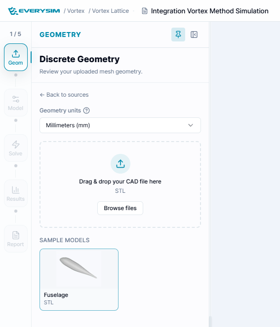
In the Upload CAD Files window, you can import the body geometry used for Rapid Aerodynamics analysis. Drag and drop an STL file into the upload area, or click Browse Files to select the CAD file from your computer. If you do not have a prepared file, you can use the provided Fuselage Sample to continue the workflow with a sample body model.
The Merge all CAD components into a single part option is enabled by default. This option is useful when the uploaded model contains multiple CAD components that should be treated as one integrated body during the rapid aerodynamic simulation.
2. Settings & Run
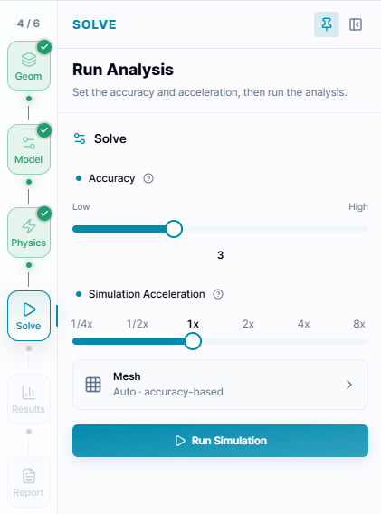
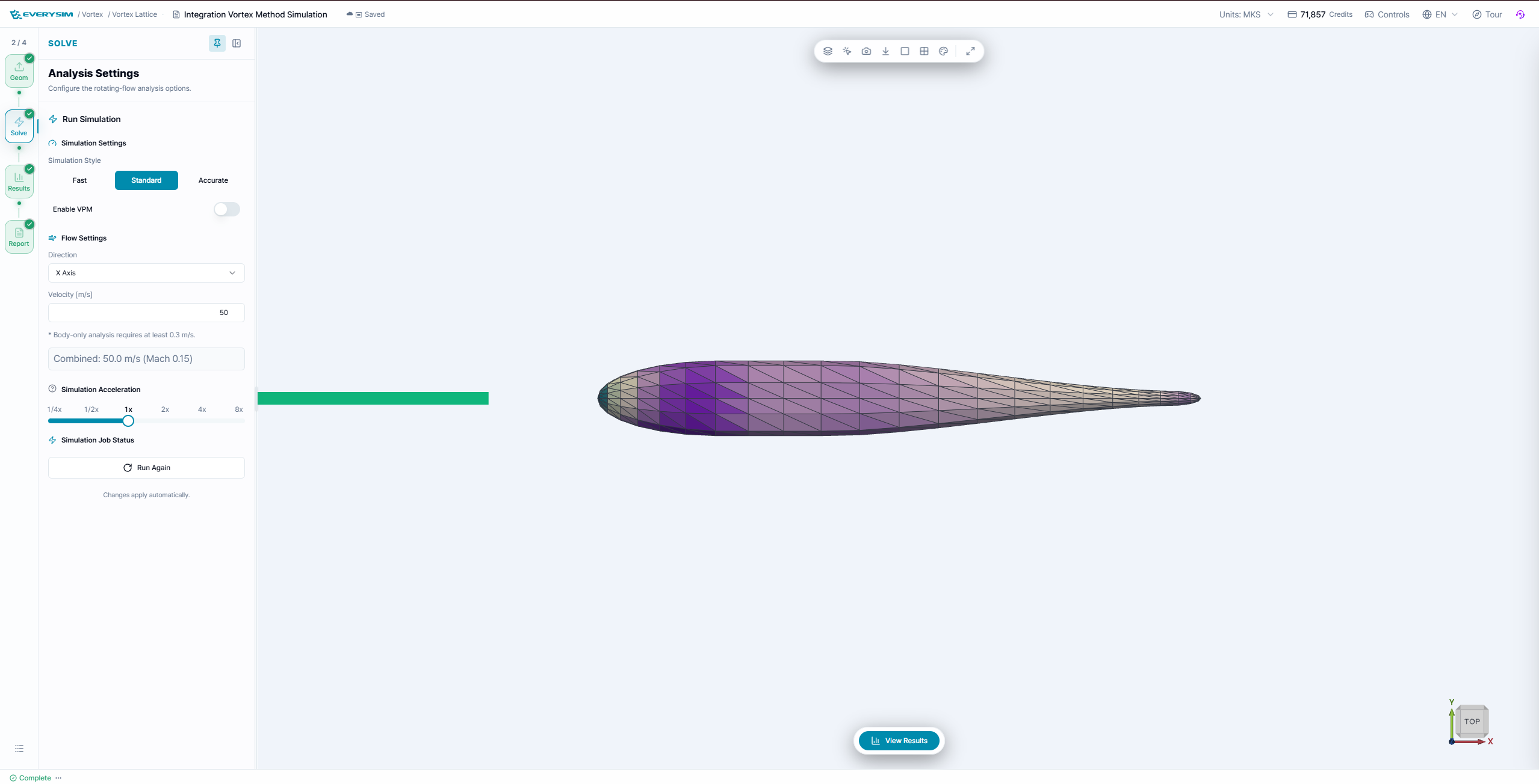
After the CAD body is imported, the model is displayed in the 3D viewer and the workflow moves to the Settings & Run step. In this panel, you can define the simulation conditions before running the analysis.
2.1. Simulation Settings
The Simulation Style controls the balance between speed and accuracy.
- Fast: Runs the simulation quickly with lower computational cost.
- Standard: Provides a balanced setting for general aerodynamic review.
- Accurate: Uses a higher accuracy setting when more detailed results are needed.
The Enable VPM option can be turned on when vortex particle method-based analysis is required.
2.2. Flow Settings
The Flow Settings section defines the incoming flow direction and velocity.
- Direction: Selects the axis direction of the incoming airflow, such as X Axis, Y Axis, Z Axis, or their negative directions.
- Velocity [m/s]: Sets the flow speed used in the simulation.
2.3. Simulation Acceleration
The Simulation Acceleration slider adjusts the computation speed level. Higher acceleration may reduce waiting time, while lower acceleration may be used when a more stable or careful simulation setup is preferred.
After checking the imported body, flow direction, velocity, and simulation style, click Run Simulation to start the Rapid Aerodynamics analysis.
3. Results
When the simulation is complete, the result is visualized directly on the imported body geometry. The colored surface contour shows how the aerodynamic quantity changes across the body surface, while the triangular surface mesh indicates how the body has been discretized for analysis.
Use the 3D viewer to rotate, zoom, and inspect the result from different angles. This allows you to check the overall aerodynamic trend around the fuselage body and identify regions where the computed values are relatively higher or lower.
4. Report
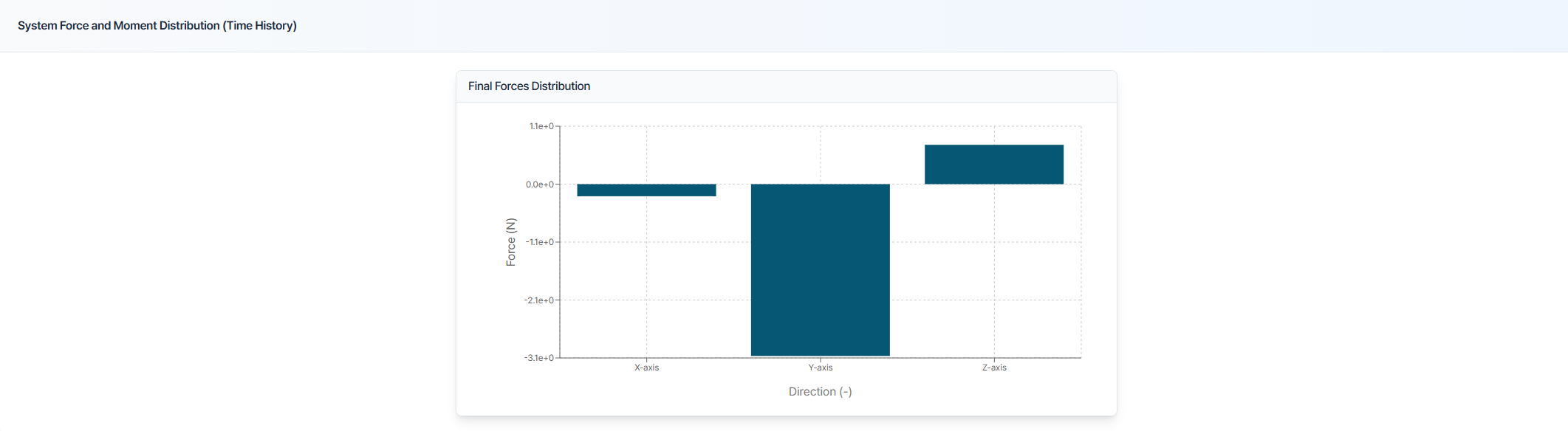
The report summarizes the final aerodynamic forces acting on the imported body. The force-distribution chart separates the integrated load into the X, Y, and Z directions so the dominant body force can be identified at a glance.
Need Assistance or Have Questions?
Frequently Asked Questions: FAQ Link
Support Inquiries: support@everysim.io