Advanced Simulation Overview
Advanced Simulation provides more reliable and meaningful results through engineering simulation technologies (CAE), including Structural Analysis (FEA), Fluid Dynamics (CFD), and Rapid Aerodynamics (Vortex Method).
1. New Project
To begin using Advanced Simulation for the first time, go to New Project and follow the steps below to properly perform your desired analysis.
1.0. Domain Type
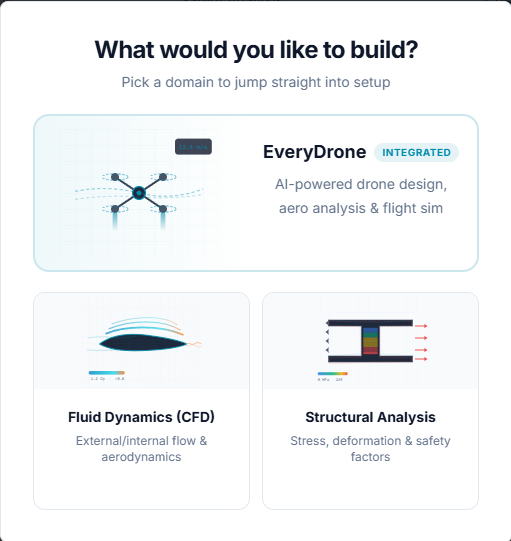
Select the domain of analysis to run:
- EveryDrone AI-powered drone design, aero analysis and flight simulation.
- Fluid Dynamics External flow, internal flow, and aerodynamics.
- Structural Analysis Stress, deformation, and safety factors.
1.1. Simulation Type
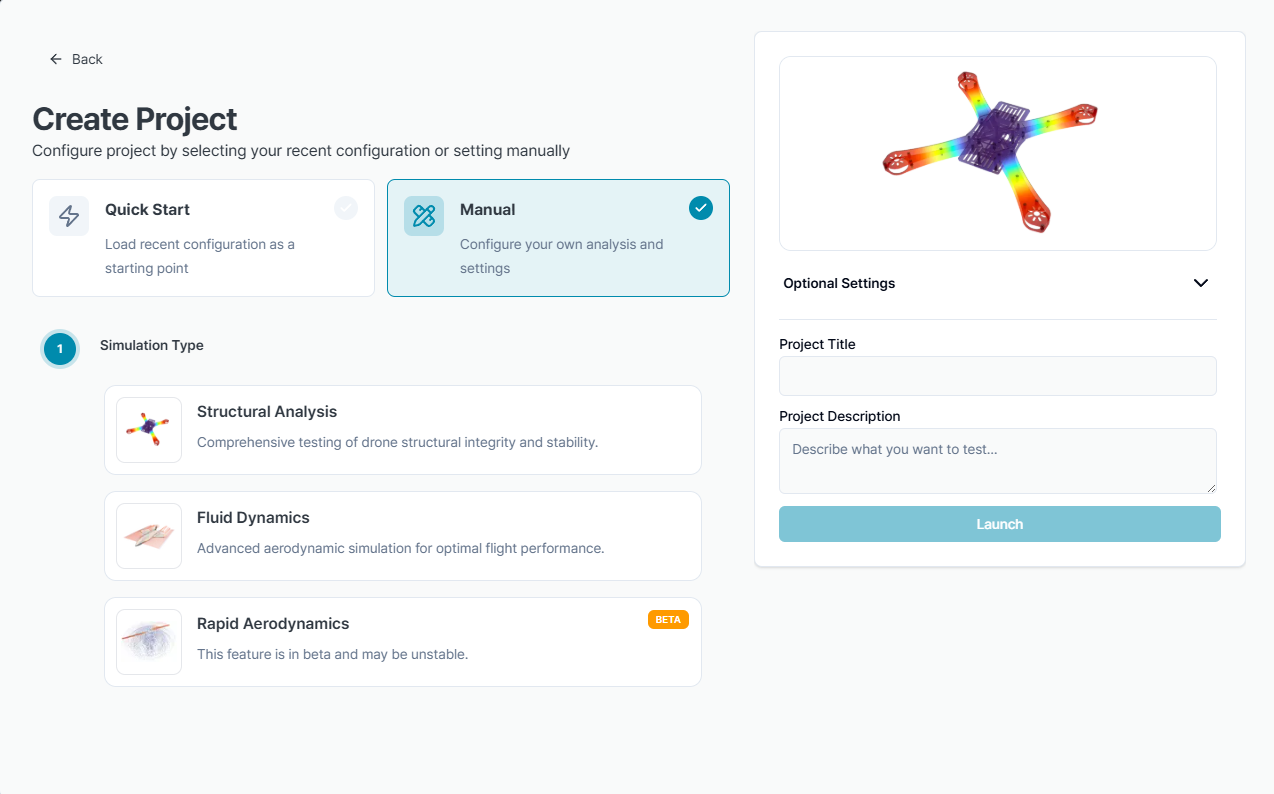
Select the type of simulation to run:
- Structural Analysis
Generates a mesh for 3D structures and analyzes stress distribution and deformation under static load conditions. Supports brep and step file formats, and can analyze compsolids consisting of multiple solids. - Fluid Dynamics
Generates a mesh for 3D fluid domains and evaluates aerodynamic characteristics using a Reynolds Averaged Navier-Stokes (RANS) equation-based solver. When importing CAD, supports brep, step, and stl file formats, assuming a single solid. - Rapid Aerodynamics
Evaluates aerodynamic characteristics using a Vortex Method solver on surface meshes for unsteady conditions. When importing CAD, uses stl file format, and the stl file cannot exceed 2,000 surface mesh elements.
Currently, Rapid Aerodynamics is in beta version, so the service may be unstable.
1.2. Testing Scope
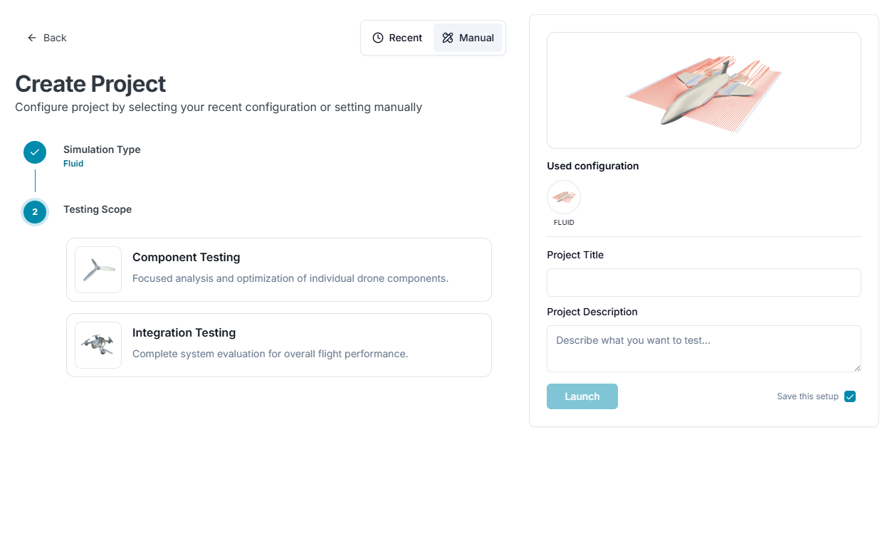
Select the test level:
- Component Testing
Provides services tailored for analyzing single components such as propellers and wings. - Integration Testing
Provides integrated or complex analysis services.
1.3. Testing Parts
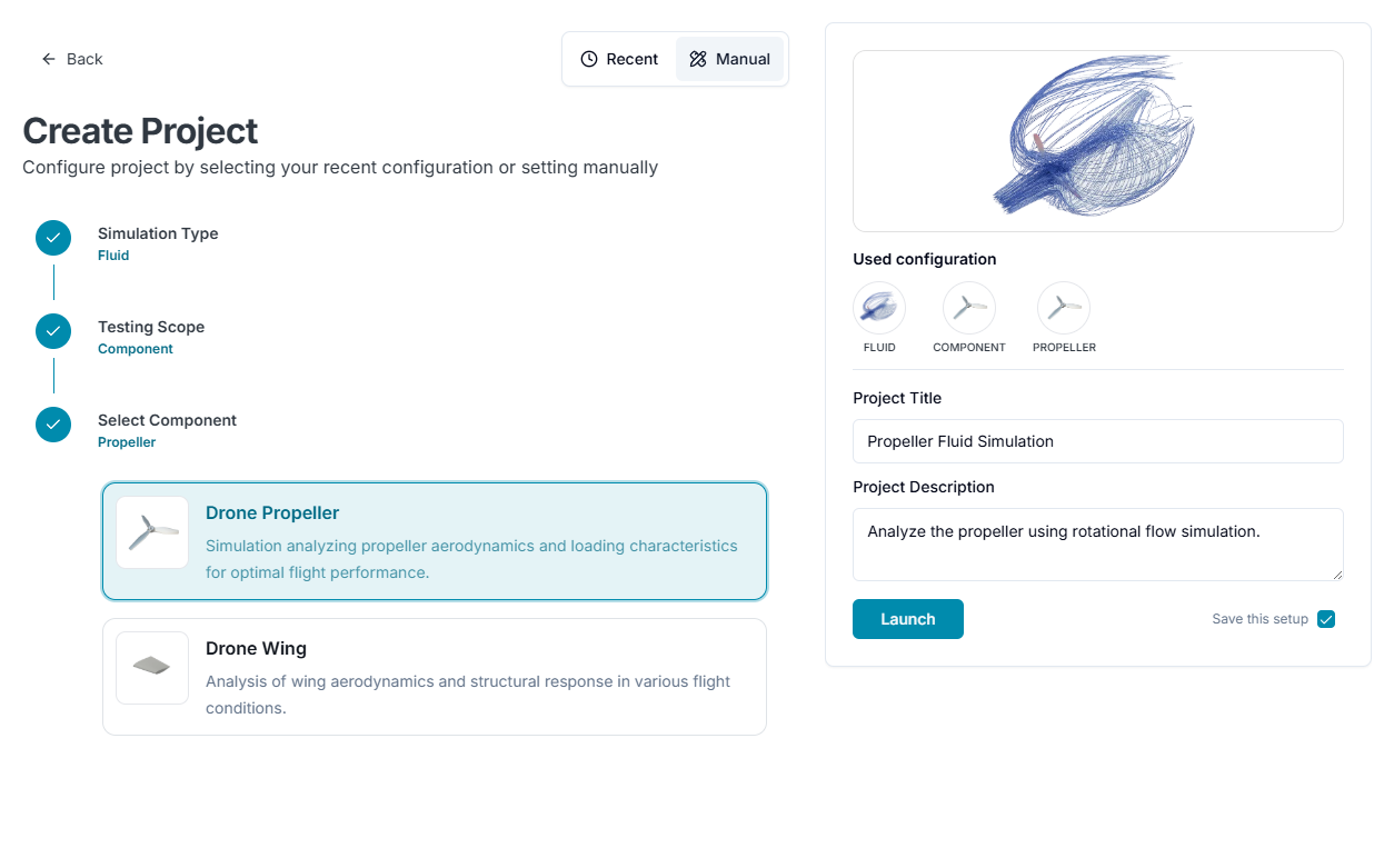
Component Testing
- Propeller, Wing: Focuses on evaluating the performance of components based on geometry, material selection, and aerodynamic characteristics.
Availability note: Rapid Aerodynamics currently supports the propeller component workflow. Rapid component-wing simulation is not available in the current system.
Integration Testing
-
Aircraft (Integration): Run a comprehensive simulation on the entire drone assembly.
-
Custom Settings(Integration): Handpick the parts or subsystems you want to simulate.
After selecting your parts, proceed to set up material properties, boundary conditions, and other parameters.
1.4. New Project Name and Description
Finally, enter the project title and description, and click Launch.
2. Workbench
When a project is created or opened, the redesigned Workbench screen is displayed. The workbench now centers the simulation workflow around guided stages, a live setup panel, a large 3D viewport, shortcut actions, project status, result tools, and a reusable tour.
The examples below show the workbench tour. Available stages and fields may differ depending on the selected analysis type, but the layout and navigation pattern are shared across Advanced Simulation workflows.
2.1. Workflow Steps
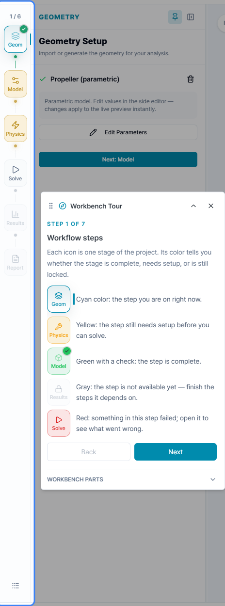
The left step rail shows the project workflow from setup to results. Each icon represents one stage of the project, such as Geometry, Model, Physics, Solve, Results, and Report. The stage count at the top shows your current progress.
- Cyan: The step you are currently editing.
- Yellow: The step still needs setup before you can continue.
- Green with a check: The step is complete.
- Gray: The step is not available yet because an earlier dependency is not finished.
- Red: Something in the step failed and needs review.
Use the step rail to understand where you are in the workflow and what must be completed before solving.
2.2. Setup Panel
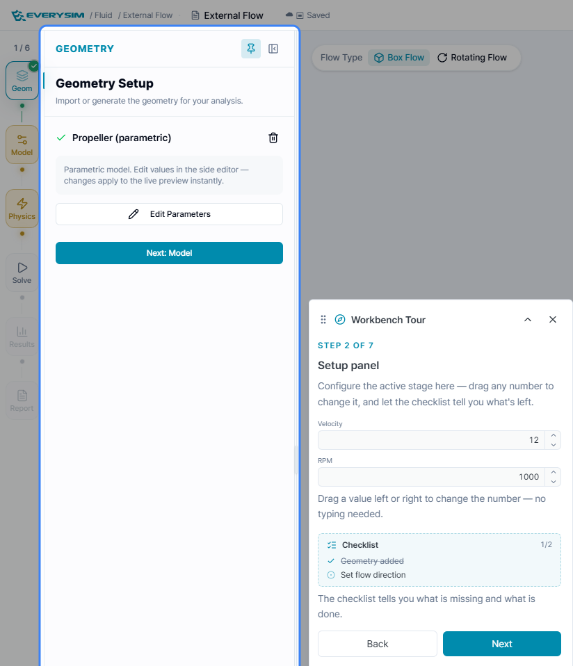
The setup panel contains the controls for the active stage. Use it to import or generate geometry, edit parametric values, configure model settings, define physics options, and run solver setup.
- The panel title and subtitle explain the active stage.
- Completed items show a check mark in the panel.
- Numeric inputs can be adjusted quickly by dragging values left or right when the field supports it.
- The checklist shows which items are complete and which requirements are still missing.
- The panel can include stage-specific controls, such as flow type options for Box Flow or Rotating Flow.
Changes apply to the live preview as you configure the active stage.
2.3. 3D Viewport
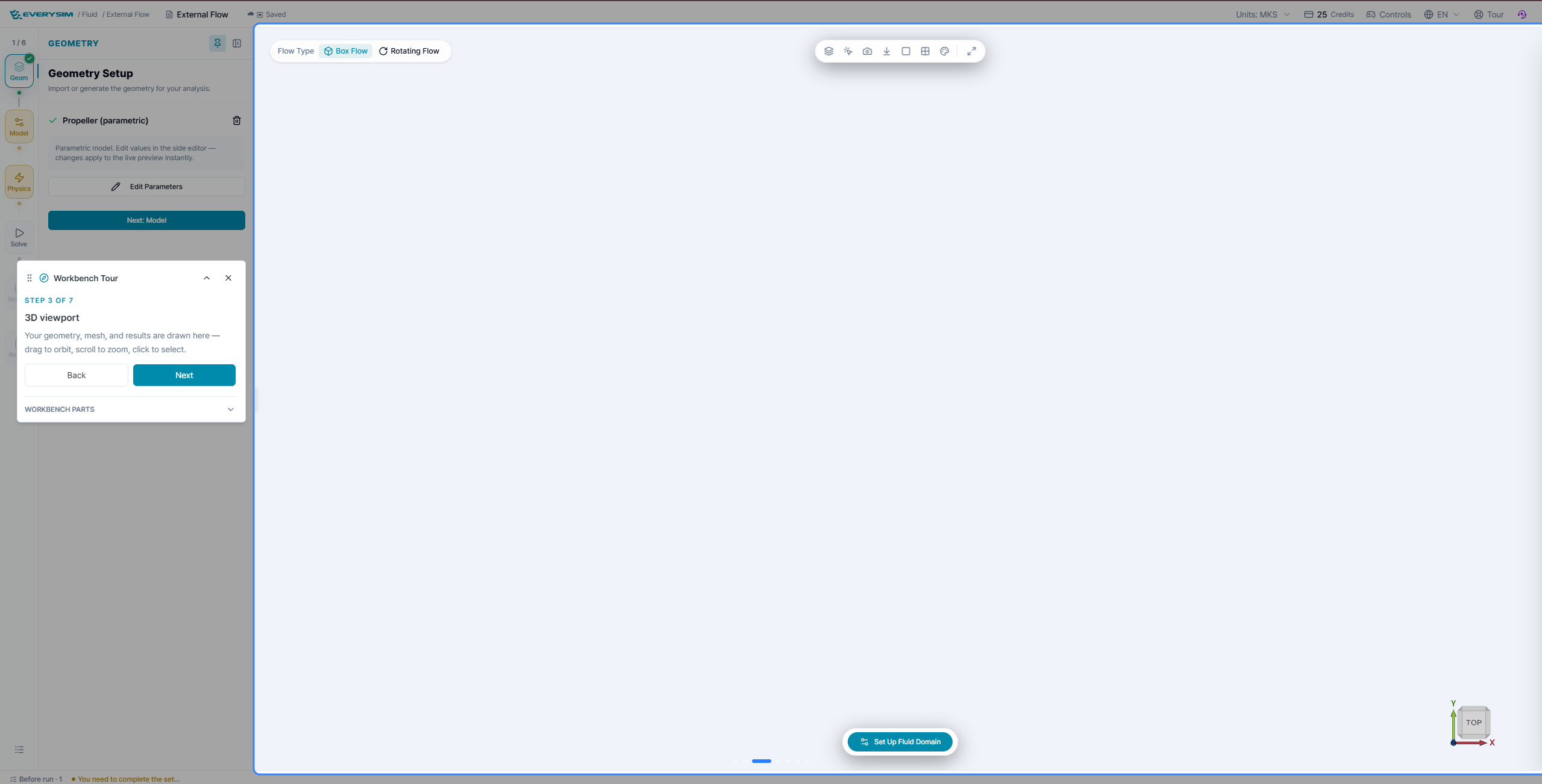
The 3D viewport is the main workspace for geometry, mesh, setup previews, and results.
- Drag to orbit the scene, scroll to zoom, and click objects to select them when selection is enabled.
- Review geometry and setup changes directly on the canvas.
- Use the view cube to confirm orientation or return to standard views such as Top or Front.
- When result data is loaded, use the viewer toolbar to inspect fields, change display modes, and capture the view.
2.4. Shortcut Bar

The shortcut bar appears near the bottom of the viewport and provides the next main action for the current workflow stage.
- The button label changes with the active stage, such as Next: Model, Set Up Fluid Domain, Go to Solve, or Run Simulation.
- Use this button when the setup panel indicates the current stage is ready.
- The shortcut keeps common next-step actions available even while you are focused on the 3D viewport.
2.5. Status Bar
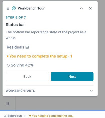
The status bar at the bottom of the workbench reports the state of the project as a whole.
- Before a run, it shows whether setup is complete or which required setup is still missing.
- During solving, it can show solver progress such as Solving 42%.
- When residual data is available, the status bar can provide access to residual information.
- Use this bar for a quick readiness and progress check without leaving the current stage.
2.6. Result Tools
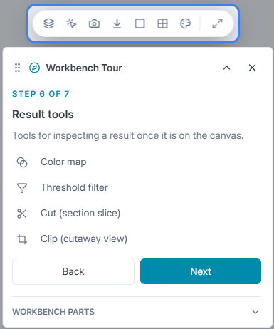
When result data is displayed on the canvas, the viewer toolbar provides tools for inspecting the result.
- Color map: Adjust how result values are colored.
- Threshold filter: Hide or isolate values based on a selected range.
- Cut: Create a section slice through the result.
- Clip: Create a cutaway view for inspecting internal or hidden regions.
The same toolbar also includes common viewer actions such as display controls, screenshot capture, download, layout options, and full-screen view.
2.7. Tour Button
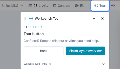
The Tour button in the top bar reopens the workbench tour whenever you need help with the layout.
- Use it when you are new to the workbench or when a workflow has unfamiliar controls.
- The tour explains the main workbench parts step by step.
- The Workbench Parts section in the tour can be expanded to review the available layout explanations.
3. Link to Detailed Design Settings
Access the following link to review the information required to perform your desired analysis.
3.1. Structural Analysis (FEA)
Component
Integration
3.2. Fluid Dynamics (CFD)
Component
Integration
3.3. Rapid Aerodynamics (Vortex Method)
Component
Integration
Need Assistance or Have Questions?
Frequently Asked Questions: FAQ Link
Support Inquiries: support@everysim.io