4.6 Fluid Dynamics: Component-Wing
1. Geometry
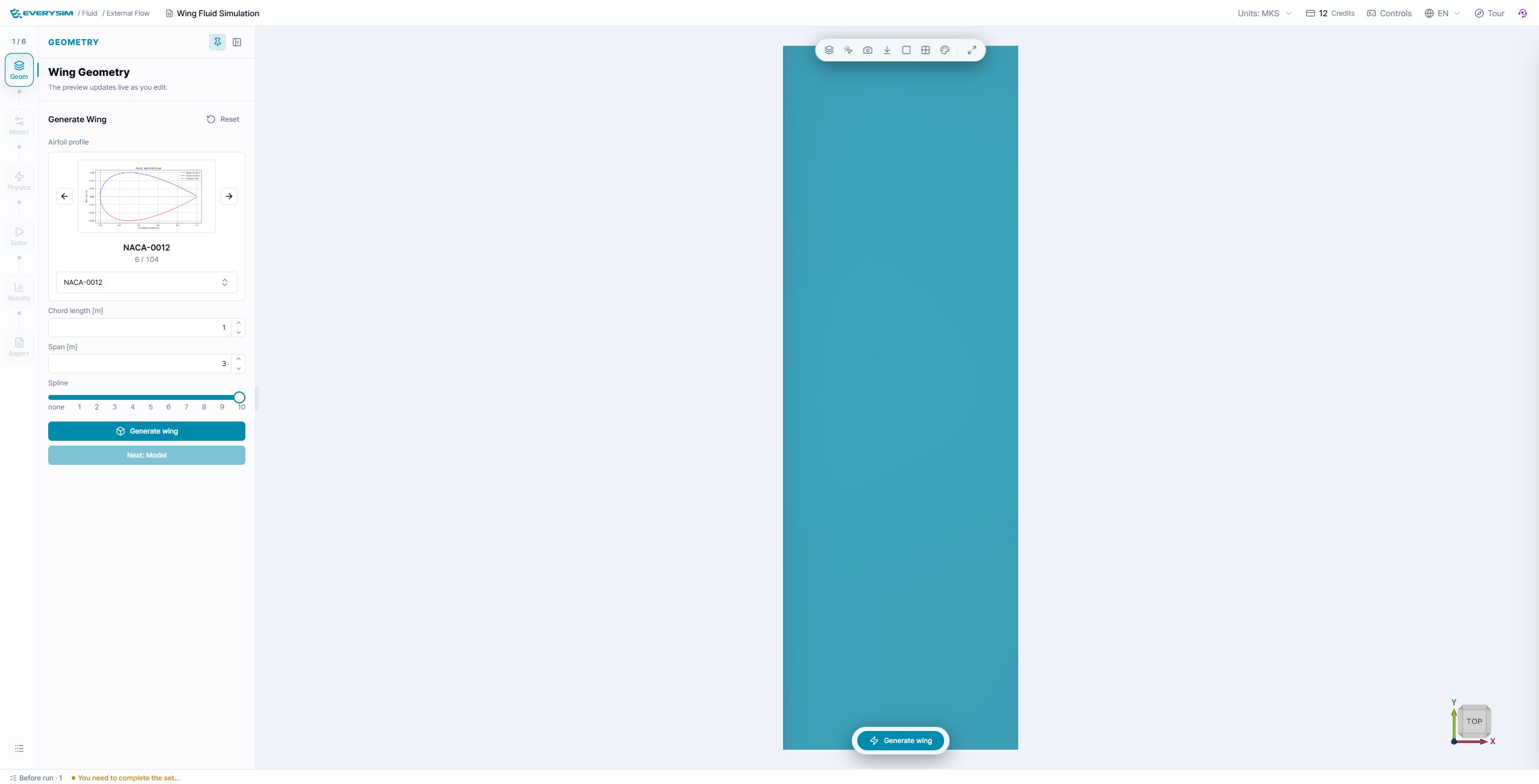
This screen shows the wing creation step for fluid dynamics analysis. The user selects an airfoil from the searchable airfoil list, checks the airfoil preview, and enters the wing generation settings. The bottom navigation bar shows that the CFD workflow proceeds through Create Wing, Create Fluid, Settings, and Run.
At the first step, create the wing geometry that will be used for fluid dynamics analysis.
1.1. Parametric Design
In the parametric wing creation interface, you can generate a wing by selecting an airfoil and defining basic geometric settings.
The main configuration items are:
- Airfoil Search: Search and select the airfoil profile to use for the wing section
- Chord Length [mm]: Defines the chord length of the wing section
- Resolution: Controls the number of points used to generate the airfoil curve
- Use Spline: Creates a smoother airfoil curve by applying spline interpolation
After selecting the airfoil and entering the geometry settings, click Create to generate the wing model.
2. Model: Fluid Domain
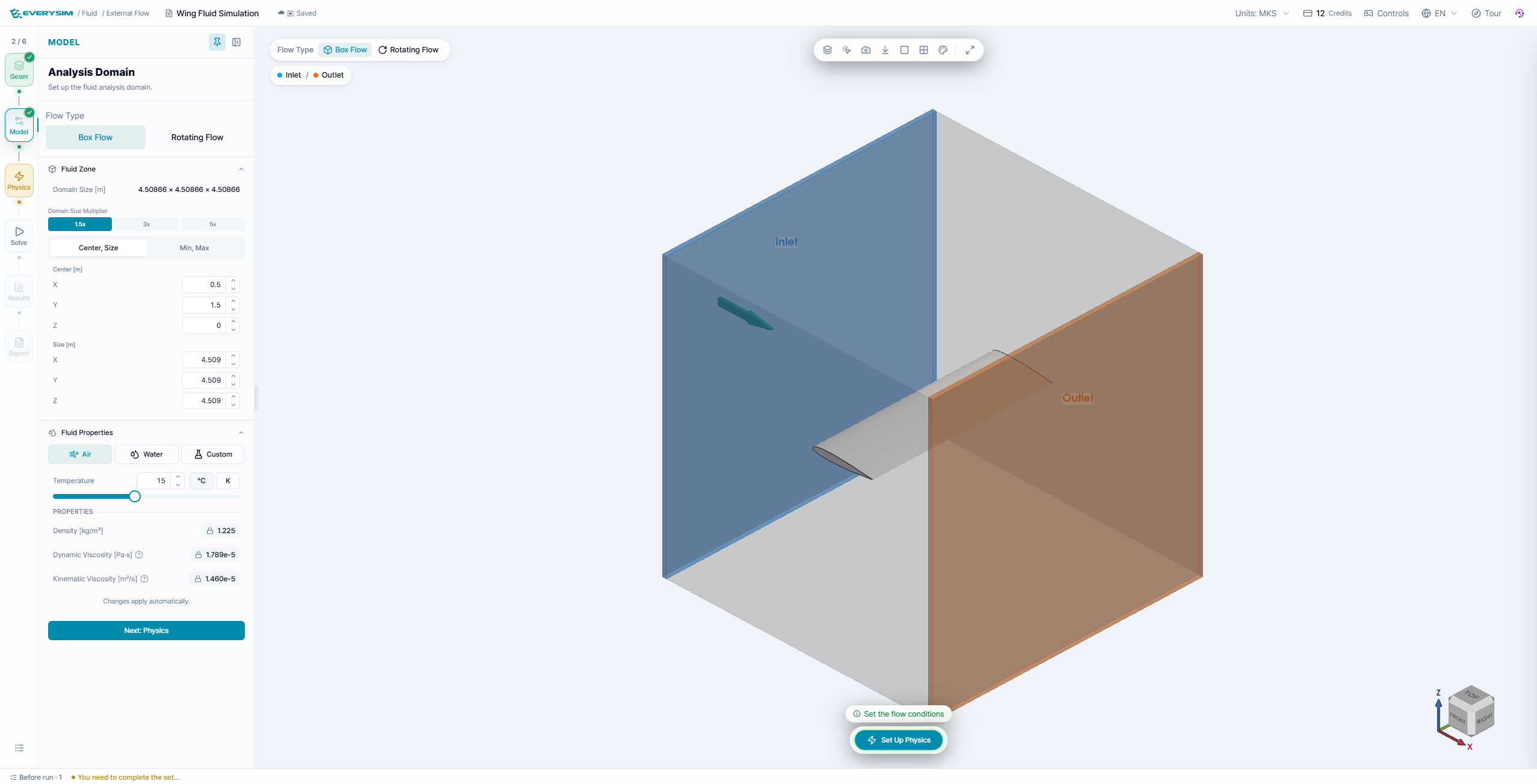
This figure shows the fluid region creation panel. The wing is placed inside a transparent rectangular fluid domain, which represents the air volume around the wing. The panel allows the user to set the analysis axis, define the center point of the domain, and specify the domain size in the X, Y, and Z directions.
In the Create Fluid step, define the fluid domain around the wing. This region represents the air volume used for aerodynamic analysis.
2.1. Axis Setup
Select the axis direction used to define the fluid region. The selected axis should match the intended analysis direction around the wing.
2.2. Center Point
Set the center position of the fluid domain.
- X: Center position in the X direction
- Y: Center position in the Y direction
- Z: Center position in the Z direction
2.3. Size
Set the size of the fluid domain.
- X: Length of the fluid region in the X direction
- Y: Length of the fluid region in the Y direction
- Z: Length of the fluid region in the Z direction
After entering the center point and size, click Create to generate the fluid region. Verify that the wing is fully contained inside the fluid domain.
3. Physics: Flow Conditions
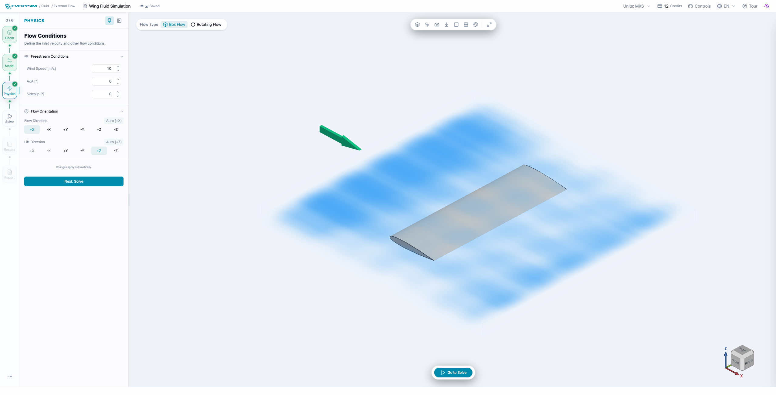
This screen shows the simulation settings panel after the wing and fluid region have been created. The panel contains wind information such as wind speed and wind direction, as well as mesh-related settings. The user can adjust the simulation accuracy and generate the mesh before starting the CFD calculation.
In the Simulation Settings step, configure wind information and mesh quality before running the analysis.
3.1. Wind Information
- Wind Speed [m/s]: Defines the inflow velocity applied to the fluid domain
- Wind Direction: Shows the direction of the incoming flow based on the selected axis setup
3.2. Simulation Accuracy
The Simulation Accuracy slider controls the mesh density and refinement level. Higher accuracy creates a finer mesh, but may increase computation time.
3.3. Mesh Options
- Enhance mesh: Improves the generated mesh quality for the selected geometry
- High-Fidelity Meshing: Enables a more detailed meshing option when available
- Enable Advanced Options: Opens additional mesh configuration options for detailed control
After completing the settings, click Generate Mesh to create the mesh for the fluid domain.
4. Solve
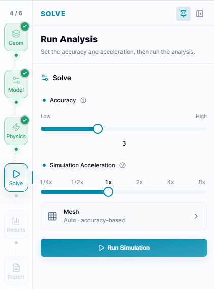
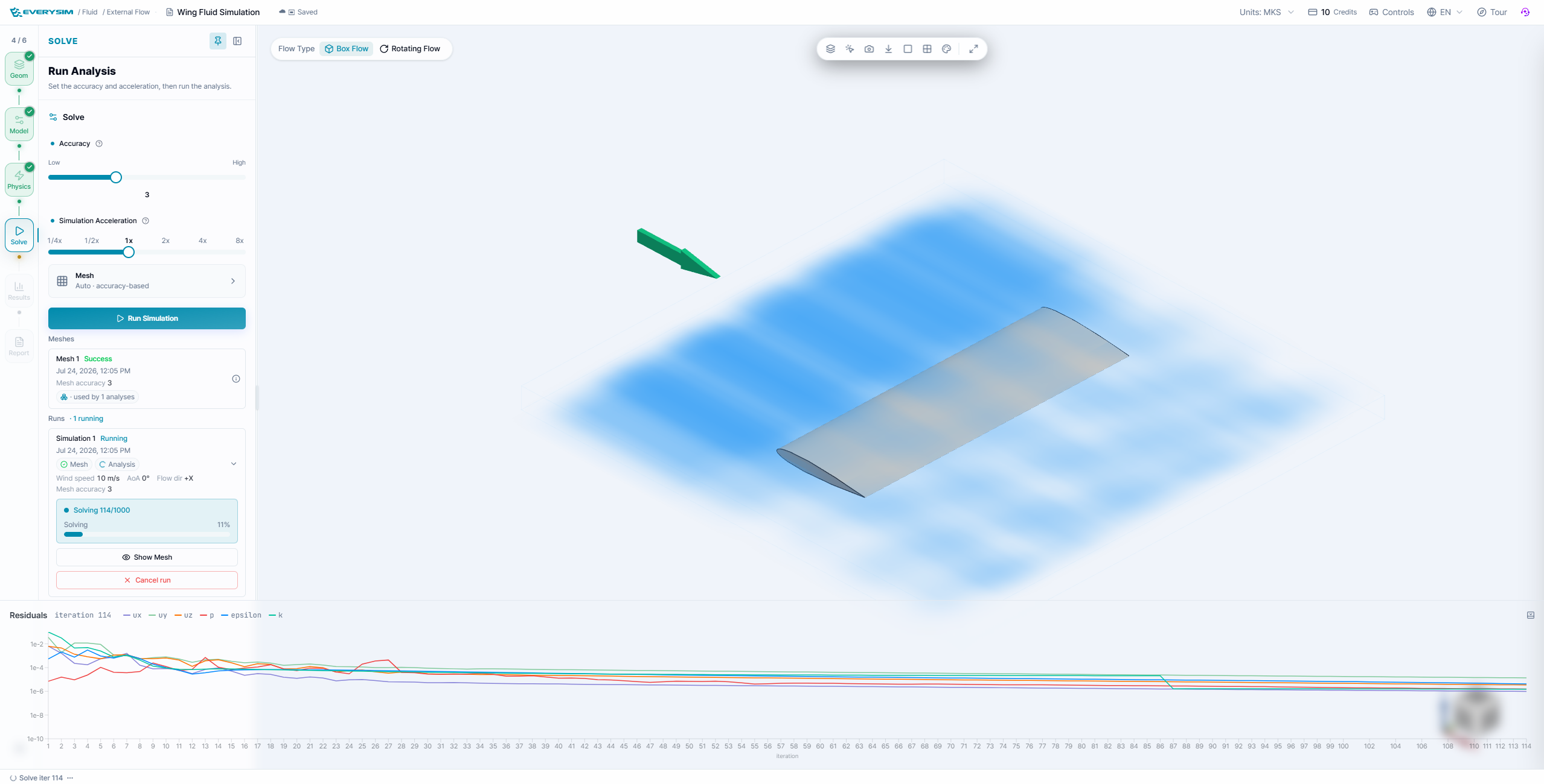
This figure shows the run step after the mesh has been generated. The 3D viewer displays the meshed fluid domain around the wing, and the Run Simulation panel allows the user to select the simulation acceleration level. The completed check marks in the workflow indicate that the model is ready to be submitted for aerodynamic analysis.
In the Run Simulation step, choose the simulation acceleration level and start the aerodynamic analysis.
- Simulation Acceleration: Controls the analysis execution speed option shown in the interface
- Run Simulation: Starts the simulation job after the mesh has been generated successfully
Before running the simulation, confirm that the Create Wing, Create Fluid, and Settings steps are complete.
5. Residuals

This screen shows the residual graph generated during the CFD simulation. Each curve represents the numerical residual of a simulation variable over the iteration history. By observing whether the curves decrease and stabilize, the user can evaluate whether the flow solution is converging properly.
When the simulation starts, you can monitor the progress in the Residuals window. Residual curves are used to check whether the numerical solution is stabilizing during the calculation.
Use the residual plot to:
- Track the progress of each solution variable
- Check whether the simulation is converging
- Identify unstable or oscillating behavior during the run
After the simulation is complete, review the aerodynamic results generated from the analysis.
6. Results
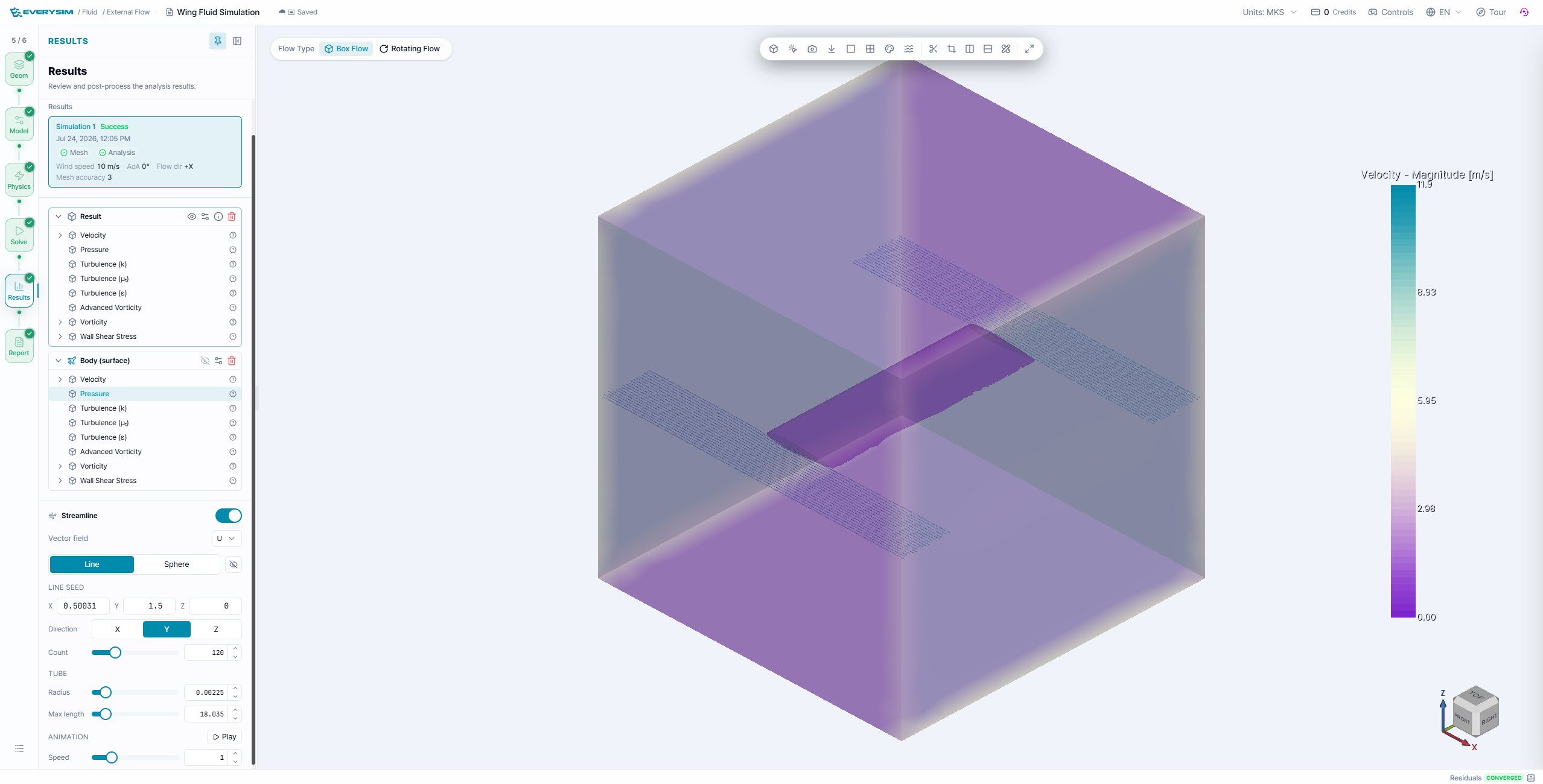
The Results stage provides volume and body-surface fields including velocity, pressure, turbulence quantities, advanced vorticity, vorticity, and wall shear stress. Select a result field in the tree, then use the legend and viewer tools to interpret its range.
Enable Streamline to seed flow lines along the selected direction. Adjust the seed position, count, tube radius, and maximum length to reveal flow direction and wake behavior without obscuring the wing. Compare surface pressure with the surrounding velocity field before drawing conclusions about lift or separation.
7. Report
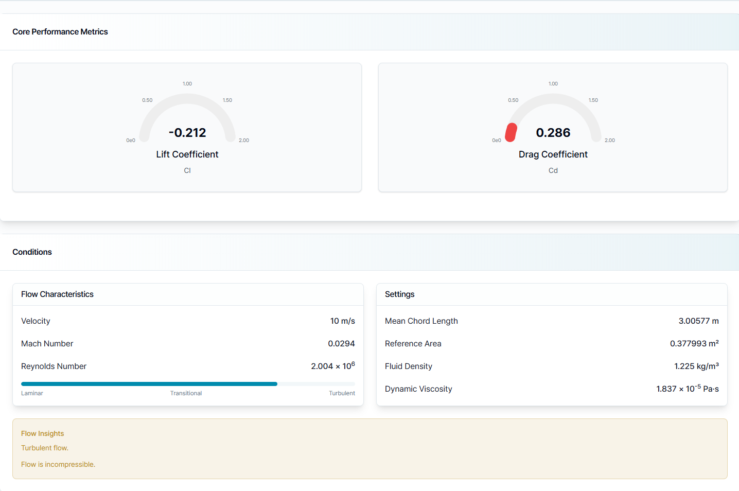
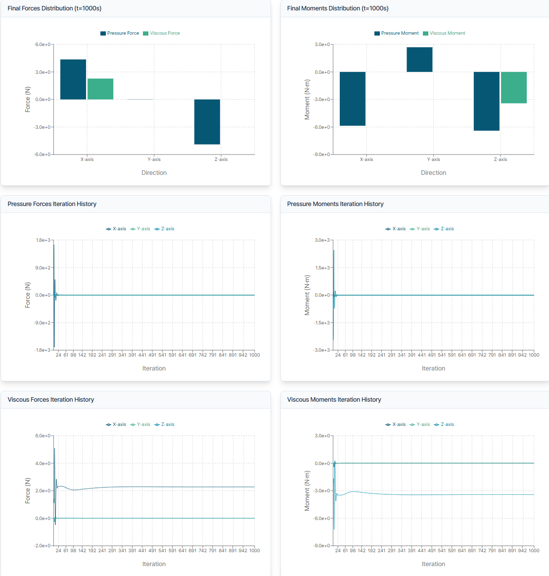
The report summarizes lift and drag coefficients, freestream velocity, Mach number, Reynolds number, reference dimensions, fluid properties, and the force-and-moment history. Flow insights identify the calculated regime and whether the incompressible-flow assumption is being used.
When comparing wing variants, keep the reference area, mean chord, flow speed, angle of attack, sideslip, domain size, accuracy, and fluid properties consistent.
Need Assistance or Have Questions?
Frequently Asked Questions: FAQ Link
Support Inquiries: support@everysim.io