4.1 Structural Analysis: Component-Propeller
1. Geometry
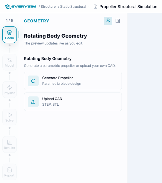
This screen shows the first step of the structural component workflow. The propeller model is displayed in the 3D viewer, and the step navigation bar at the bottom shows the full analysis sequence: Create Propeller, Material, Constraints, Loads, Mesh, and Run. At this stage, the user prepares the propeller geometry before assigning material properties or analysis conditions.
At the first step, create the propeller geometry that will be used for structural analysis.
1.1. Parametric Design
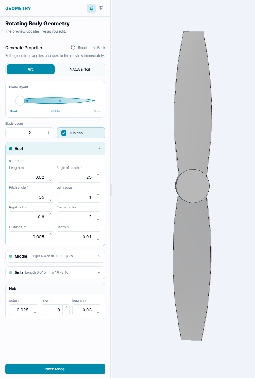
This figure shows the parametric propeller design window. The user can define the number of blades, configure the hub, and enter blade section parameters. The right side of the interface shows a preview of the generated propeller shape, allowing the user to visually check whether the geometry changes are applied correctly before creating the final model.
In the parametric propeller creation interface, you can define the propeller geometry by entering cross-section and rotation axis parameters. The interface is organized into four tabs: Root Section, Mid Section, Tip Section, and Rotation Axis.
Blade Count: Specifies the number of blades.
1.1.1. Section (Root, Mid, Tip)
The Root Section, Mid Section, and Tip Section tabs share the same parameters and define the cross-sectional shape at three positions along the blade span. The key parameters for each section are:
- Width: Chord length at this section
- Alpha: Angle between the chord line and reference axis
- Beta: Sweep or twist angle at this position
- Leading Edge Radius: Relative radius of leading edge curvature
- Trailing Edge Radius: Relative radius of trailing edge curvature
- Thickness: Maximum airfoil thickness
- Max Thickness Position: Location of maximum thickness along the chord line
- Depth: Radial distance from hub center to this section
1.1.2. Rotation Axis Parameters
The Rotation Axis tab allows you to configure hub geometry and blade count settings.
- Blade Count: Total number of blades
- Use Cap: Whether to include a hemispherical solid at the hub center
- Hub Outer Diameter: Hub outer radius
- Hub Inner Diameter: Hub inner radius
- Hub Height: Height in the rotation axis direction
After entering the required values, click Create to generate the propeller geometry.
2. Model: Material Properties
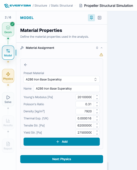
This screen shows the Assign Material step after the propeller geometry has been created. The propeller is visible in the viewer, and the material panel on the right contains editable fields for mechanical properties such as Young's modulus, density, Poisson's ratio, tensile strength, and yield strength. The selected propeller element is listed in the Selected Elements table, confirming that the material will be applied to the correct solid body.
In the Assign Material step, define the material properties for the selected propeller element. You can enter the material properties manually or use Preset Materials when an existing material is available.
The material input fields include:
- Material Name: Name of the material assigned to the selected element
- Young's Modulus: Elastic stiffness of the material
- Poisson's Ratio: Ratio between lateral and axial strain
- Density: Mass per unit volume of the material
- Thermal Expansion: Expansion coefficient used when thermal effects are considered
- Tensile Strength: Maximum tensile stress before failure
- Yield Strength: Stress level where permanent deformation begins
Select the target propeller element from the canvas, verify that it appears in the Selected Elements table, and click Assign.
3. Physics: Constraints
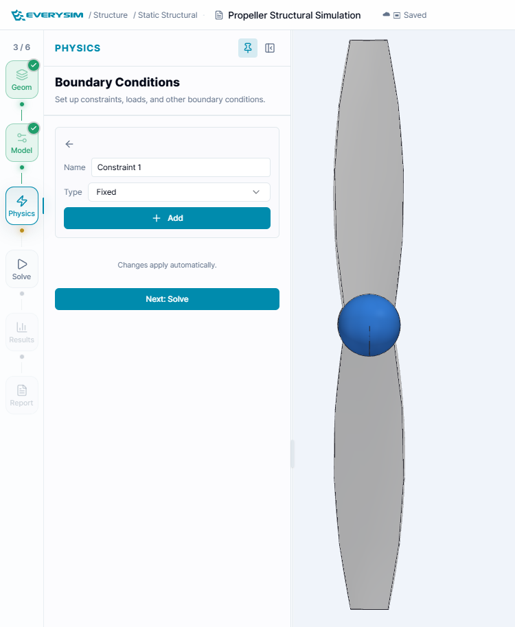
This figure shows the constraint assignment interface. A blade region is highlighted in the 3D viewer, while the right-side panels provide two constraint options: Fixed Support and Enforced Displacement. The constraint list at the bottom confirms which boundary conditions have already been added to the model.
The constraint assignment process supports two methods: Fixed Supports and Enforced Displacement.
3.1. Fixed Supports
Use Fixed Supports to lock selected faces or regions of the propeller. This is commonly applied to the hub or mounting area to represent the part connected to the motor shaft.
3.2. Enforced Displacement
Use Enforced Displacement when a specific displacement should be applied to the selected element.
- DX [mm]: Displacement in the X direction
- DY [mm]: Displacement in the Y direction
- DZ [mm]: Displacement in the Z direction
After selecting the target element, verify the selected element list and click Assign.
4. Physics: Loads
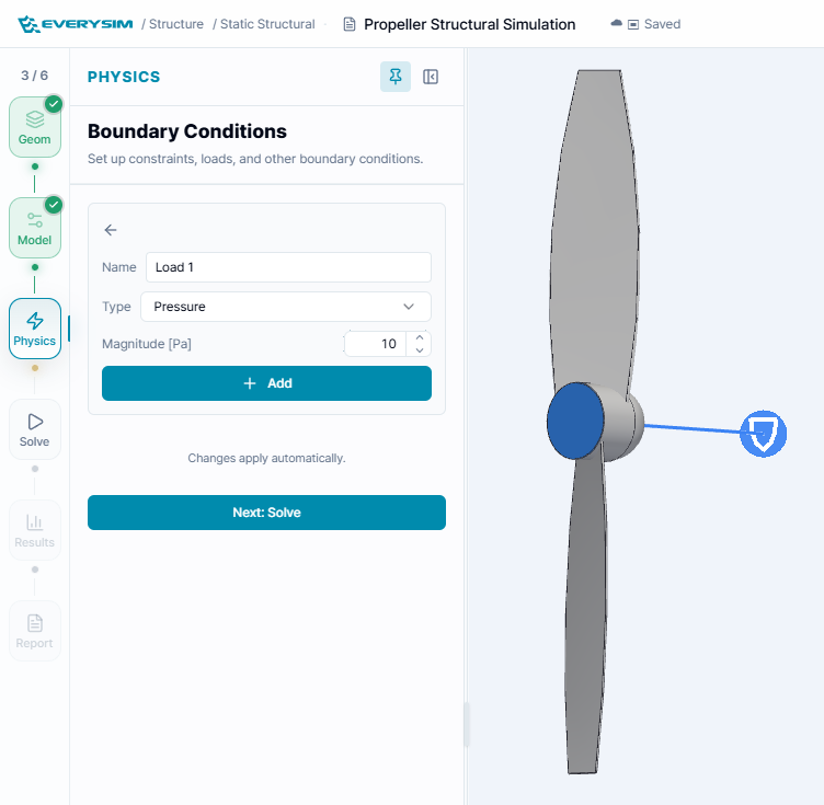
This screen shows the load assignment step. The selected region of the propeller is highlighted in the viewer, and the load panels allow the user to apply either a distributed Pressure or a directional Facial Force. This step defines the external forces that the propeller will experience during the structural analysis.
The load assignment process supports two methods: Pressure and Facial Force.
4.1. Pressure
Use Pressure to apply a distributed load normal to the selected face. Enter the pressure value in N/m² and assign it to the selected propeller surface.
4.2. Facial Force
Use Facial Force to apply force components directly to the selected face.
- FX [N]: Force in the X direction
- FY [N]: Force in the Y direction
- FZ [N]: Force in the Z direction
After selecting the target face, verify that the selected element appears in the table and click Assign.
5. Solve: Mesh and Accuracy
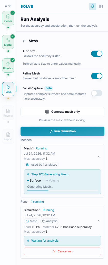
This figure shows the mesh configuration panel before mesh generation. The user can control the Simulation Accuracy level with a slider and optionally enable enhanced meshing, high-fidelity meshing, or advanced mesh options. These settings determine how detailed the generated finite element mesh will be.
In the Simulation Setting step, configure the mesh and accuracy level before running the analysis.
5.1. Simulation Accuracy
The Simulation Accuracy slider controls the mesh resolution. A higher value creates a finer mesh and may improve result accuracy, but it can also increase computation time.
5.2. Mesh Options
- Enhance mesh: Improves the generated mesh quality for the selected geometry
- High-Fidelity Meshing: Enables a more detailed meshing option when available
- Enable Advanced Options: Opens additional mesh configuration options for detailed control
Click Generate Mesh after configuring the settings.
The Meshes card records mesh generation status, accuracy, and the analyses that use the mesh. A running analysis appears separately in the Runs list so mesh progress and solver progress can be reviewed independently.
After the mesh generation is complete, check that the mesh job status is displayed as Success. You can regenerate the mesh if the geometry, material, constraints, or loads are changed.
6. Run Analysis
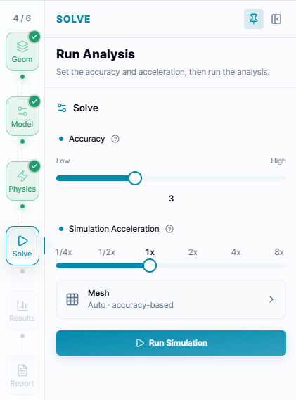
This figure shows the final run step of the structural analysis workflow. The previous setup stages are marked as complete, and the Run Simulation button is available. When the simulation job status is ready, the user can start the analysis to calculate the structural response of the propeller under the assigned materials, constraints, and loads.
In the Run Simulation step, verify that the previous steps have been completed successfully, then click Run Simulation to start the structural analysis job.
After the simulation finishes, review the generated results to evaluate whether the propeller can withstand the assigned constraints and loads.
7. Results
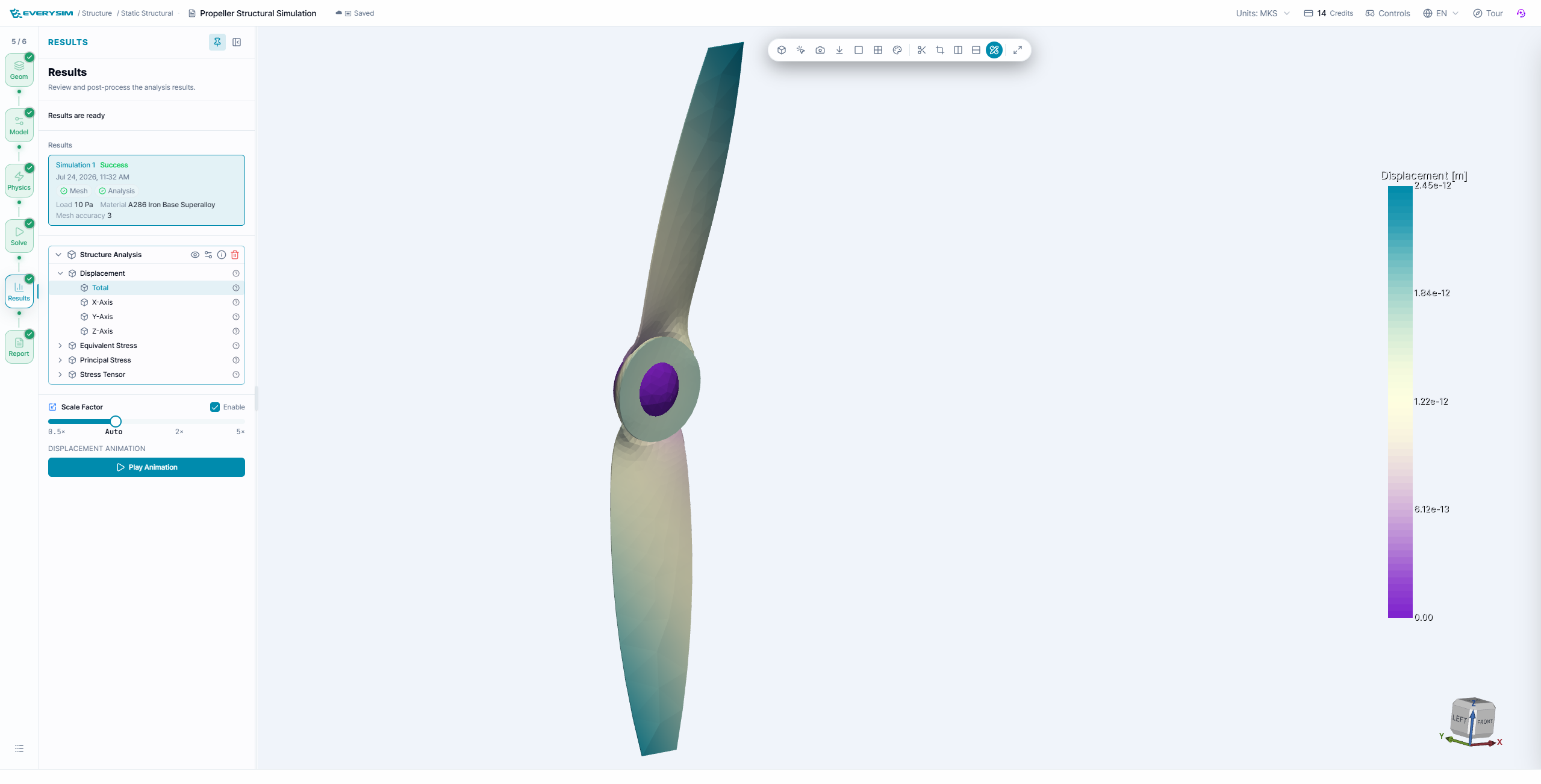
The Results stage displays the solved structural fields on the propeller and keeps the successful simulation record visible in the setup panel. Expand Structure Analysis to inspect:
- Displacement: total displacement and its X-, Y-, and Z-axis components.
- Equivalent Stress: the von Mises stress field used for ductile-material assessment.
- Principal Stress: the principal stress components at each location.
- Stress Tensor: the complete tensor representation for detailed review.
For displacement results, enable the Scale Factor when the physical deformation is too small to see at true scale. Use Play Animation to inspect the deformed shape through the displayed motion cycle. Always read the color legend and units before comparing regions.
8. Report
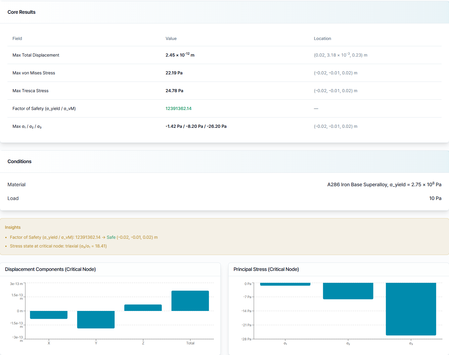
The structural report summarizes the simulation in a form that can be reviewed without manipulating the 3D result:
- Max Total Displacement: largest displacement magnitude and its location.
- Max von Mises Stress and Max Tresca Stress: peak equivalent-stress measures and their locations.
- Factor of Safety: material yield strength divided by the maximum von Mises stress.
- Principal stresses: the maximum, intermediate, and minimum principal values at the critical point.
- Conditions: the material and applied load used for the run.
- Insights and charts: critical-node displacement components and principal-stress comparisons.
Use the report together with the 3D result. A high factor of safety does not replace checks for realistic constraints, correct load direction, appropriate material data, and adequate mesh resolution.
Need Assistance or Have Questions?
Frequently Asked Questions: FAQ Link
Support Inquiries: support@everysim.io