CAD Guidelines for Simulation
This page provides guidelines for preparing and importing CAD files for Structural Analysis (FEA), Fluid Dynamics (CFD), and Rapid Aerodynamics (Vortex Method) simulations.
Selecting the right CAD format and ensuring geometry quality are critical first steps before running any simulation. Poor CAD quality can lead to mesh generation failures or unreliable results.
1. Supported File Formats by Simulation Type
| Simulation Type | Supported Formats | Notes |
|---|---|---|
| Structural Analysis (FEA) | .step, .stl | Multi-solid supported |
| Fluid Dynamics (CFD) | .step, .stl | Treated as a single solid |
| Rapid Aerodynamics (VM) | .stl | Max 4,000 surface mesh elements |
If you are unsure which format to use, .step is the most universally compatible option for both FEA and CFD workflows.
2. Structural Analysis (FEA) CAD Requirements
2.1. Supported Formats
.step(STP) — ISO 10303 standard format. The most commonly used exchange format, supported by virtually all CAD applications..stl— Tessellated surface mesh format. Usable for structural analysis, but shape distortion may occur on curved surfaces; only single parts are considered. Set a high tessellation resolution when exporting.
2.2. Geometry Requirements
- Multi-body supported: FEA simulation can analyze geometries consisting of multiple solids. Ensure shared faces between solids are properly merged to allow load transfer across interfaces.
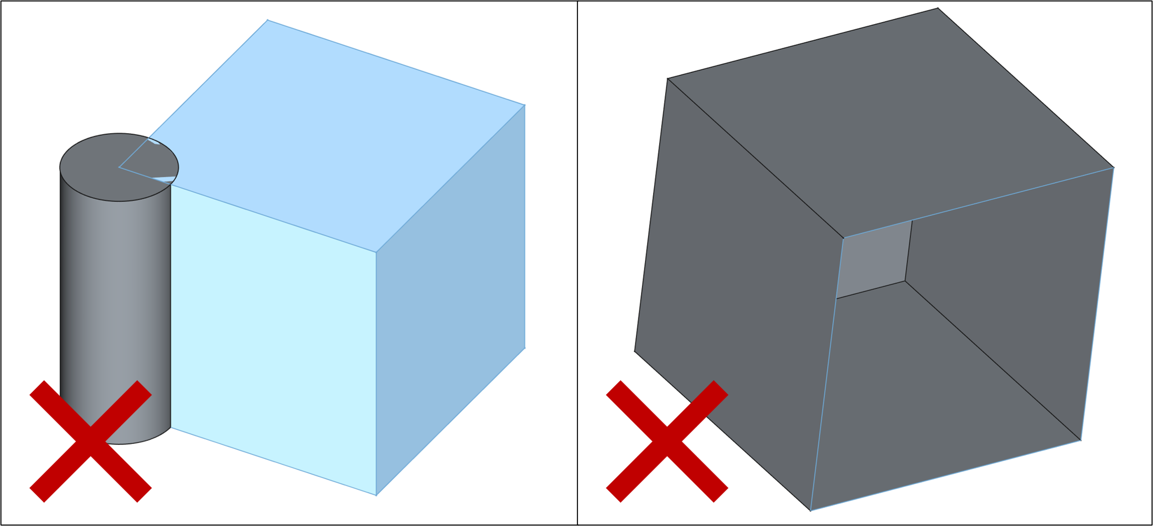
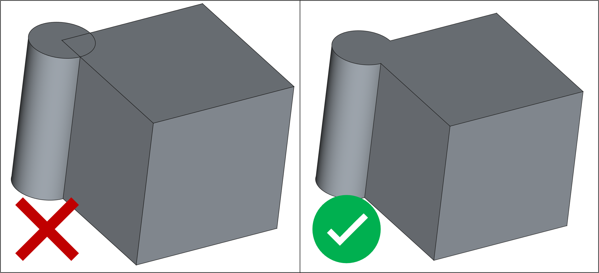
- No self-intersections: Faces must not penetrate or intersect each other.
- Closed volumes: Each solid must be fully enclosed with no open surfaces.
- Clean topology: Avoid duplicated faces, zero-area faces, or degenerate edges.
2.3. Sample CAD File
A sample CAD file is provided for testing FEA workflows.
- FEA Example.step — Sample CAD for FEA structural analysis
3. Fluid Dynamics (CFD) CAD Requirements
3.1. Supported Formats
.step(STP) — ISO 10303 standard format. The most commonly used exchange format, supported by virtually all CAD applications..stl— Tessellated surface mesh format. Acceptable for CFD but shape distortion may occur on curved surfaces. Set a high tessellation resolution when exporting.
3.2. Geometry Requirements
- Single solid: The CFD solver assumes the imported geometry is a single, unified solid. If your model has multiple bodies, merge or boolean-union them before importing.
- Watertight (closed) surface: The geometry must have no open edges or holes.
- No self-intersections: Surfaces must not overlap or intersect.
- Outward-facing normals (for
.stl): All face normals must point consistently toward the exterior of the geometry. - Simplified geometry: Remove internal cavities, fasteners, and small fillets if they are not aerodynamically relevant. These features increase mesh complexity without contributing to flow accuracy.
3.3. Sample CAD File
- ONERA-M6.step — NASA NPARC Alliance Validation Archive benchmark model
4. Rapid Aerodynamics (Vortex Method) CAD Requirements
4.1. Supported Format
.stl— Only STL format is supported. The surface mesh included in the STL file is used directly as the panel mesh for the Vortex Method solver.
4.2. Geometry Requirements
- Maximum 4,000 surface elements: The
.stlfile must contain no more than 4,000 triangular faces. Exceeding this limit will prevent the simulation from starting. - Closed surface: The surface must be watertight (no open edges).
- Outward-facing normals: All triangle normals must point consistently toward the exterior of the geometry.
4.3. Sample CAD File
A sample STL file is provided for testing Rapid Aerodynamics workflows.
- Skysurfer Vortex.stl — Sample CAD for Vortex Method analysis
5. General CAD Preparation Checklist
Before uploading your CAD file to any simulation type, run through the following checklist:
- File is saved in the correct format for the selected simulation type
- Geometry is a closed, watertight solid (no open edges or holes)
- No self-intersecting faces
- All face normals point outward (especially for
.stl) - For CFD/VM: geometry is a single merged solid
- For VM: element count is ≤ 4,000
- Unnecessary internal features have been removed to simplify meshing
- Units are consistent (meters recommended)
Need Assistance or Have Questions?
Frequently Asked Questions: FAQ Link
Support Inquiries: support@everysim.io