4.5 Fluid Dynamics: Component-Propeller
1. Propeller Creation
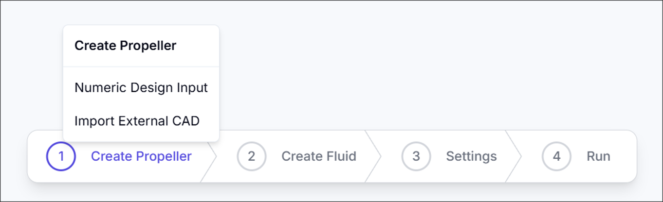
The propeller creation process supports two methods: Parametric Design and External CAD Import.
1.1. Parametric Design
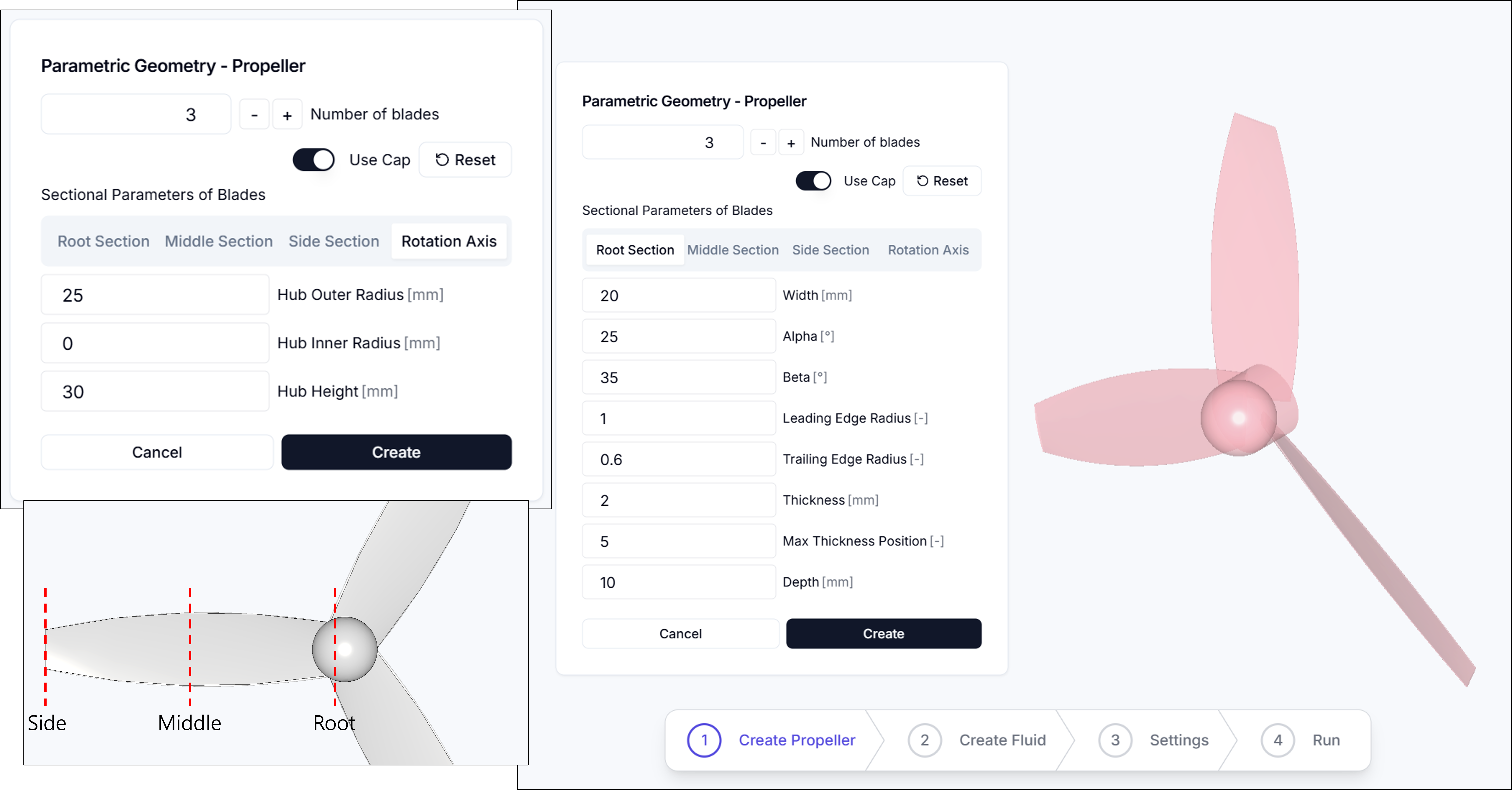
In the parametric propeller creation interface, you can define the propeller geometry by entering cross-section and rotation axis parameters. The interface is organized into four tabs: Root Section, Mid Section, Tip Section, and Rotation Axis.
Blade Count: Specifies the number of blades.
1.1.1. Section (Root, Mid, Tip)
The Root Section, Mid Section, and Tip Section tabs share the same parameters and define the cross-sectional shape at three positions along the blade span. The key parameters for each section are:
- Width: Chord length at this section
- Alpha: Angle between the chord line and reference axis
- Beta: Sweep or twist angle at this position
- Leading Edge Radius: Relative radius of leading edge curvature
- Trailing Edge Radius: Relative radius of trailing edge curvature
- Thickness: Maximum airfoil thickness
- Max Thickness Position: Location of maximum thickness along the chord line
- Depth: Radial distance from hub center to this section
1.1.2. Rotation Axis Parameters
The Rotation Axis tab allows you to configure hub geometry and blade count settings.
- Blade Count: Total number of blades
- Use Cap: Whether to include a hemispherical solid at the hub center
- Hub Outer Diameter: Hub outer radius
- Hub Inner Diameter: Hub inner radius
- Hub Height: Height in the rotation axis direction
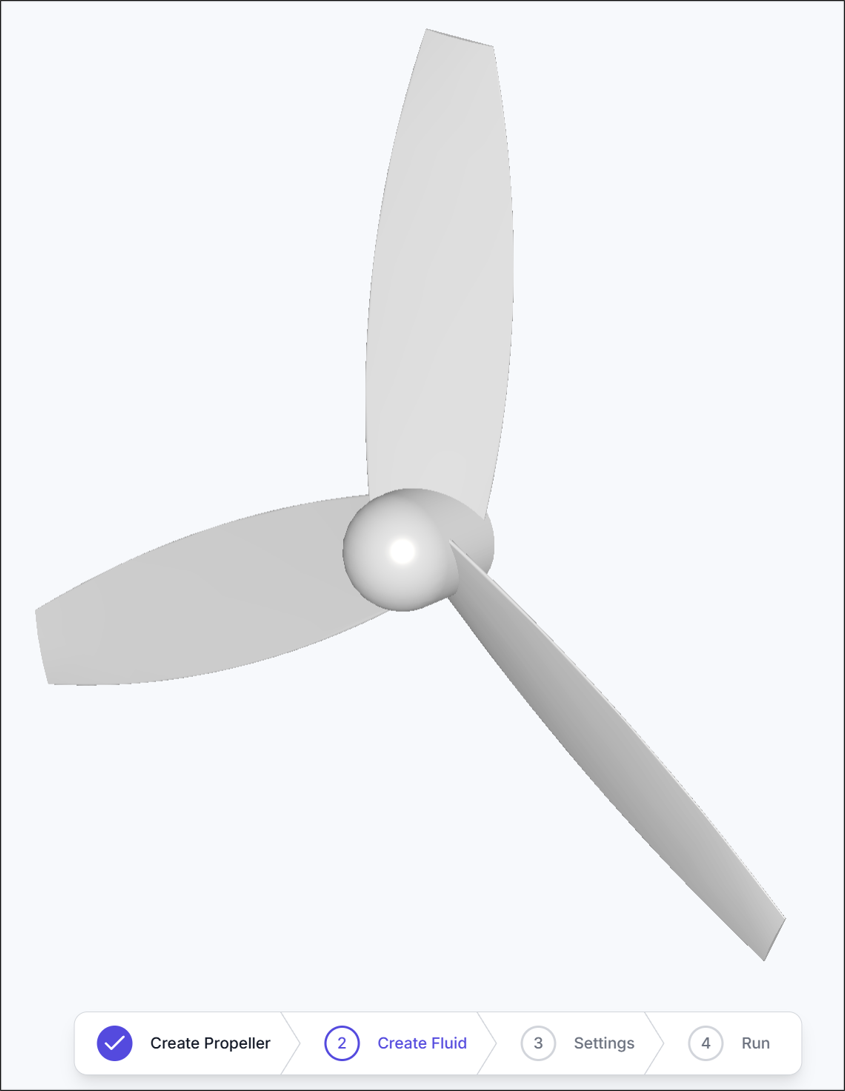
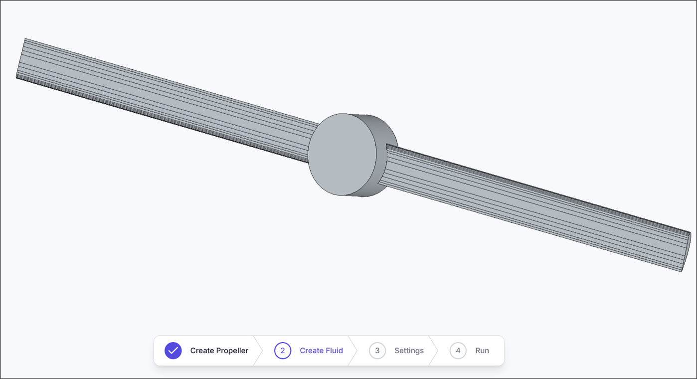
After entering all values correctly, click the Create button to generate the geometry as shown above.
1.2. External CAD Import
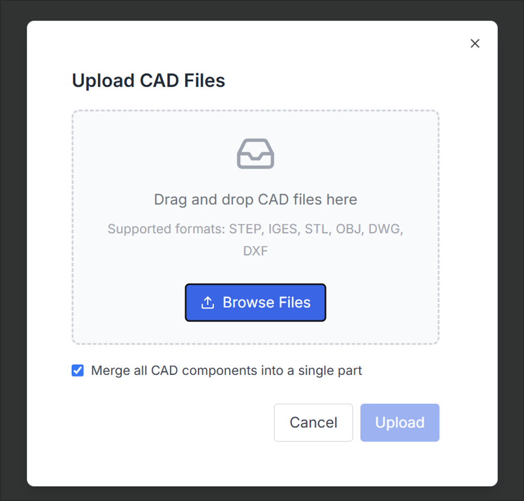
If you have a CAD file prepared, click Browse Files to select and import the file as shown.
If the import is successful, the CAD geometry will be displayed as shown.
2. Create Fluid Region
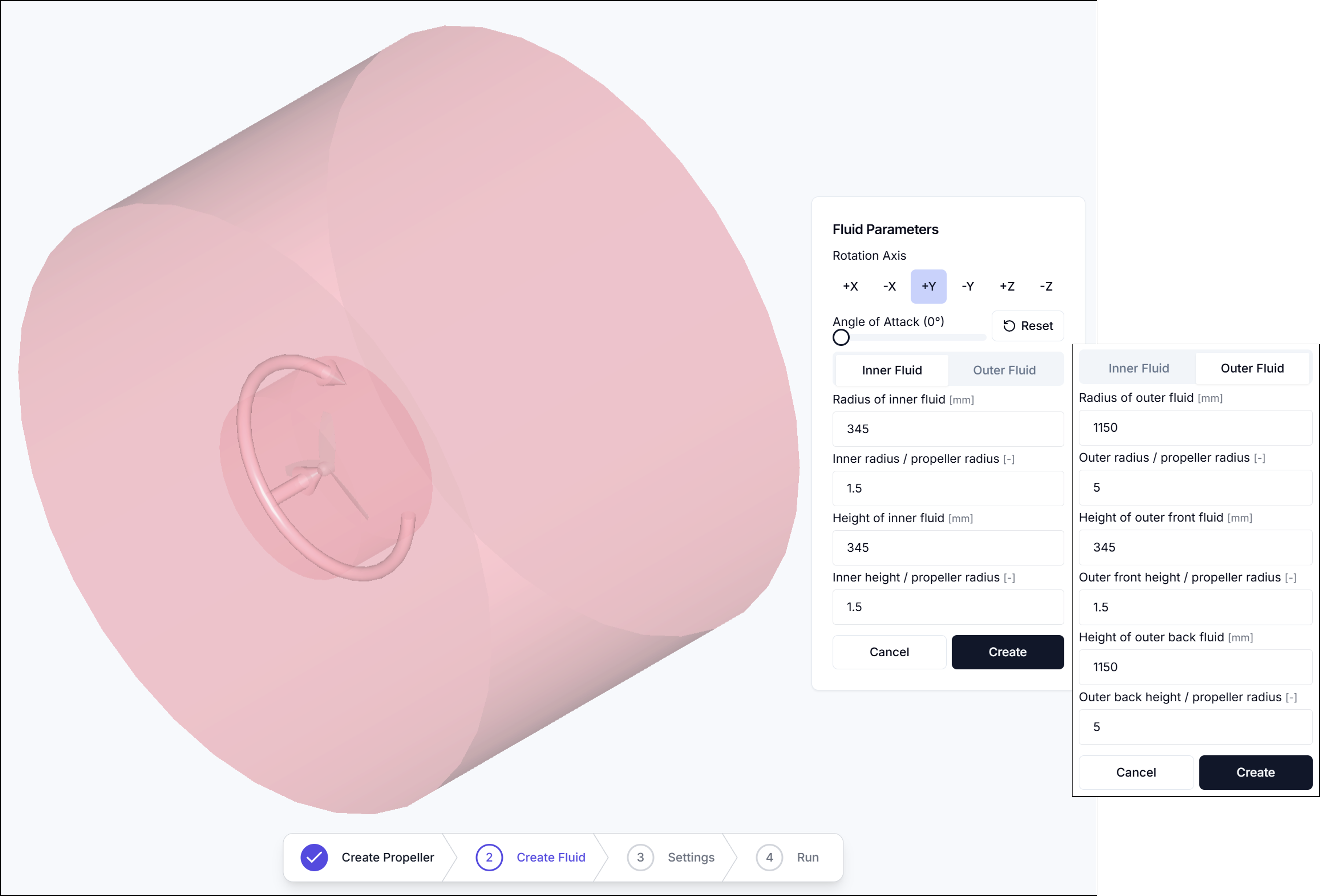
In the Create Fluid Region step, a rotating flow field is created based on the propeller's rotation axis, and the external fluid region is also defined.
2.1. Rotation Axis
- Specifies the rotation axis for the flow field.
2.2. Angle of Attack
- Specifies the angle between the incoming flow and the propeller disc normal. Adjusting this value changes the direction of the internal flow field around the rotating propeller.
The fluid region is divided into two areas: the Inner Fluid where rotation occurs, and the surrounding Outer Fluid. Detailed settings are as follows.
2.3. Inner Fluid
- Inner Fluid Radius [mm]: Radius of the inner fluid region that wraps around and rotates with the propeller (mm)
- Inner Radius/Propeller Radius: Ratio of inner fluid radius to propeller radius (used for normalization)
- Inner Fluid Length [mm]: Axial length of the inner rotating fluid region (mm)
- Inner Height/Propeller Radius: Ratio of inner fluid height to propeller radius
2.4. Outer Fluid
- Outer Fluid Radius [mm]: Radius of the outer (stationary) fluid region (mm)
- Outer Radius/Propeller Radius: Ratio of outer fluid radius to propeller radius
- Outer Front Fluid Length [mm]: Axial length of the outer fluid region in front of the propeller (mm)
- Outer Front Height/Propeller Radius: Ratio of outer front fluid height to propeller radius
- Outer Rear Fluid Length [mm]: Axial length of the outer fluid region behind the propeller (mm)
- Outer Rear Height/Propeller Radius: Ratio of outer rear fluid height to propeller radius
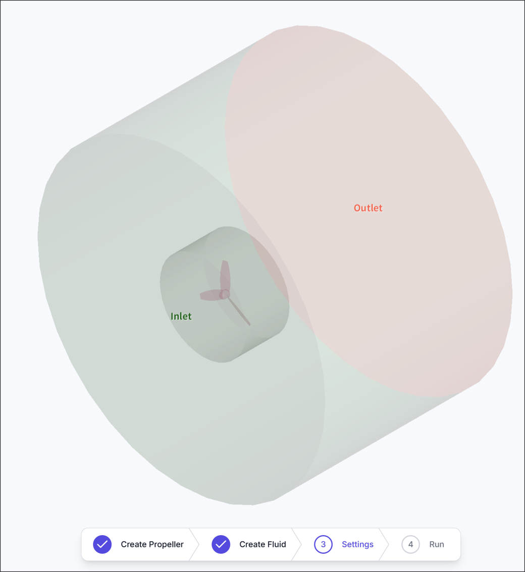
If settings are correct, the fluid region will be created as shown.
3. Simulation Settings
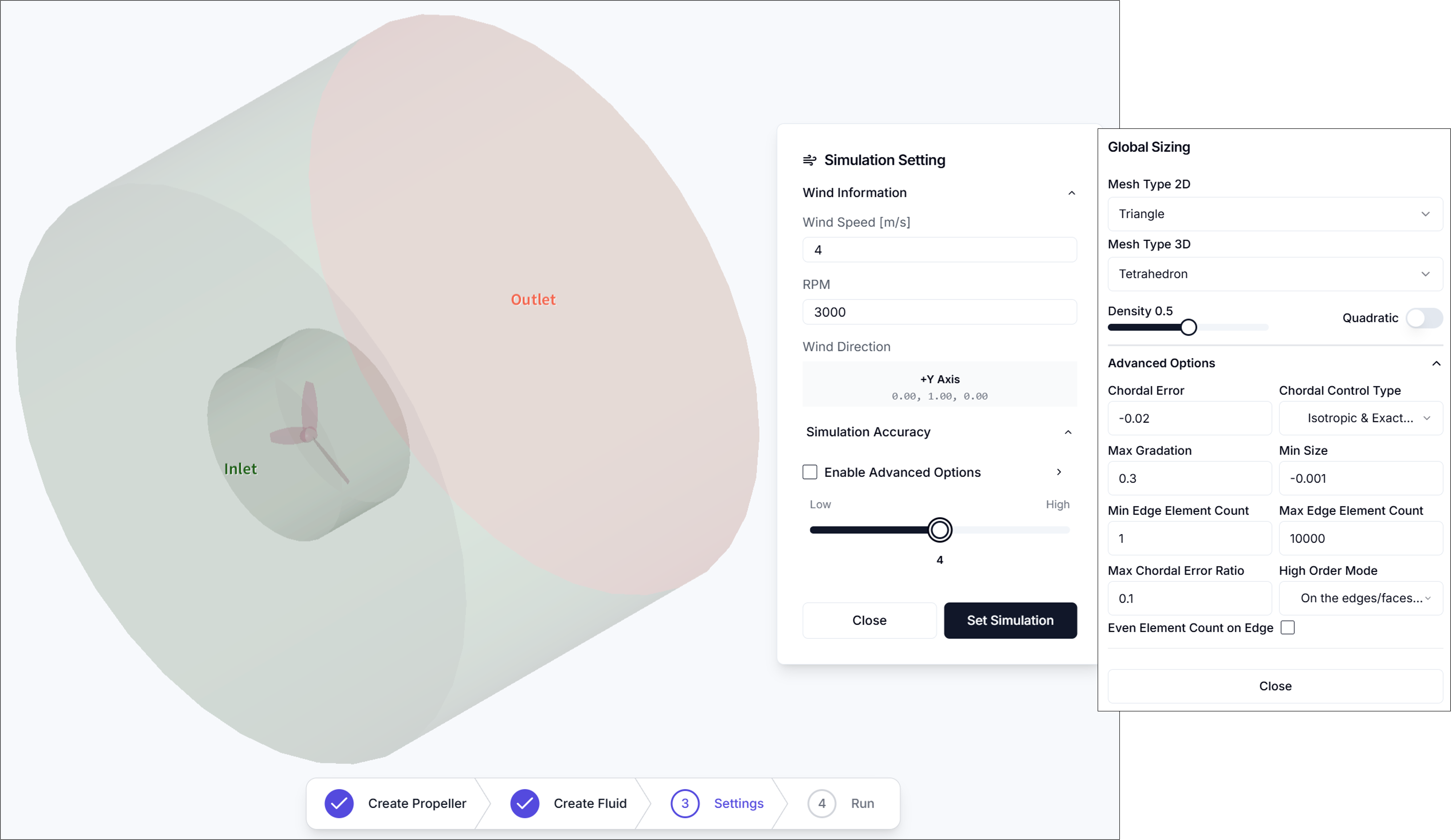
3.1. Wind Speed [m/s]
- Specifies the inflow velocity at the inlet boundary.
3.2. RPM
- Sets the propeller's revolutions per minute (RPM).
3.3. Simulation Accuracy
- Sets mesh density and refinement level.
- Enabling advanced options allows detailed mesh configuration.
3.3.1. Mesh Parameters (Advanced Options)
-
2D Mesh Type
- Select surface mesh type applied to faces
- Triangle
- QuadDominant
- Quadrangle
- Select surface mesh type applied to faces
-
3D Mesh Type
- Select volume mesh type applied inside the fluid region
- Tetrahedron
- HexaDominant
- Hexahedron
- Select volume mesh type applied inside the fluid region
-
Density
- Adjust overall mesh density with a slider (higher values create finer meshes)
-
Chordal Error
- Maximum allowable deviation between mesh edges and actual geometry (lower values improve geometric fidelity)
-
Chordal Control Type
- Select how chordal error is applied
- No Curvature
- Isotropic & Approximate Curvature
- Anisotropic & Approximate Curvature
- Isotropic & Exact Curvature
- Anisotropic & Exact Curvature
- Select how chordal error is applied
-
Max Gradation
- Maximum size ratio between adjacent elements (controls mesh transition smoothness)
-
Min Size
- Minimum edge length for generated mesh elements
-
Min Edge Element Count
- Minimum number of elements per edge
-
Max Edge Element Count
- Maximum number of elements per edge
-
Max Chordal Error Ratio
- Maximum ratio between actual chordal error and target value
-
High Order Mode
- High-order treatment method for curved surfaces
- Interpolated
- On the edges/faces but not equidistant
- On the edges/faces but equidistant
- High-order treatment method for curved surfaces
-
Even Element Count on Edge
- Force even element count on edges for symmetry or periodicity (when needed)
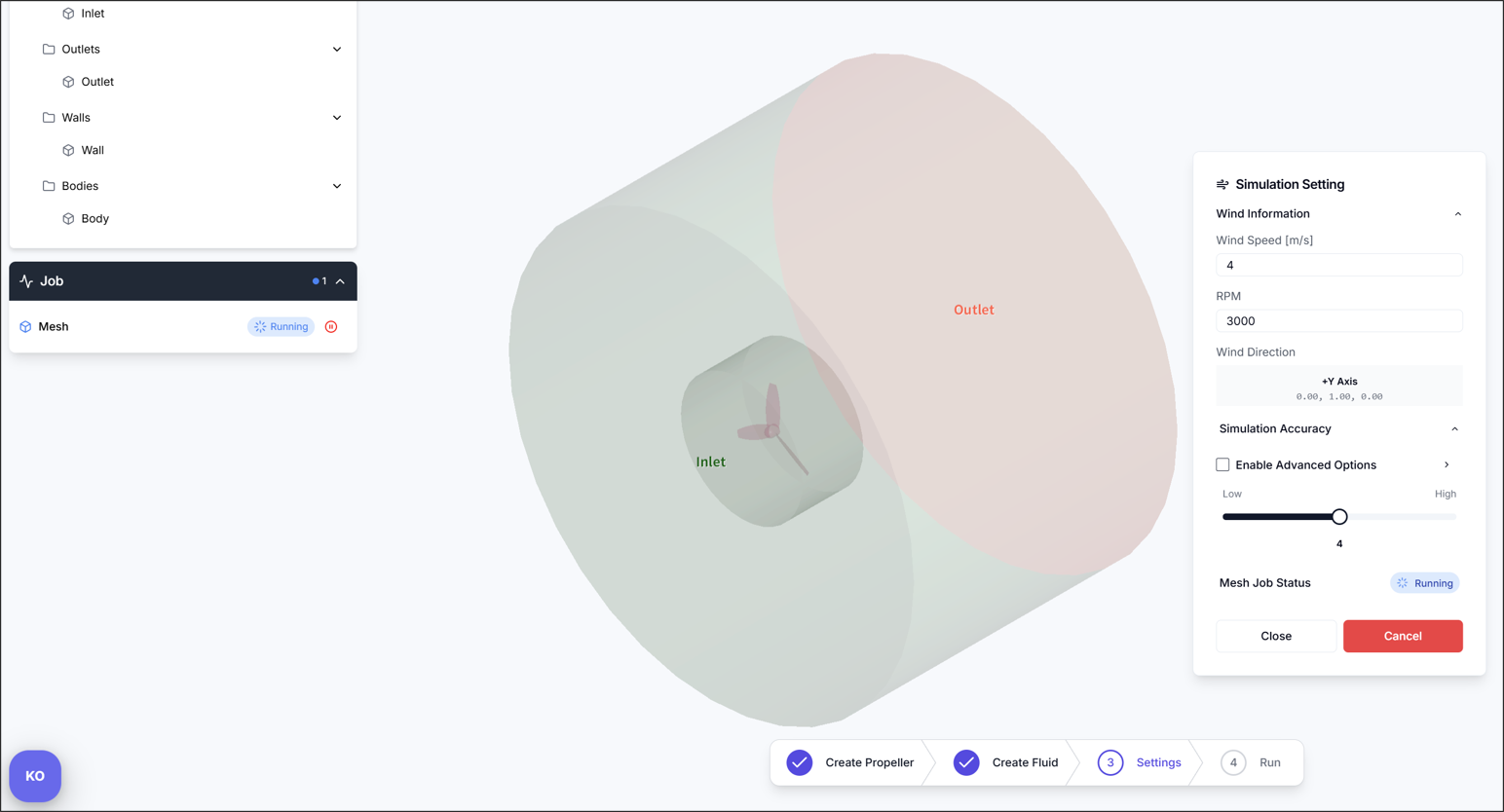
After completing settings, click the Set Simulation button to create the mesh job.
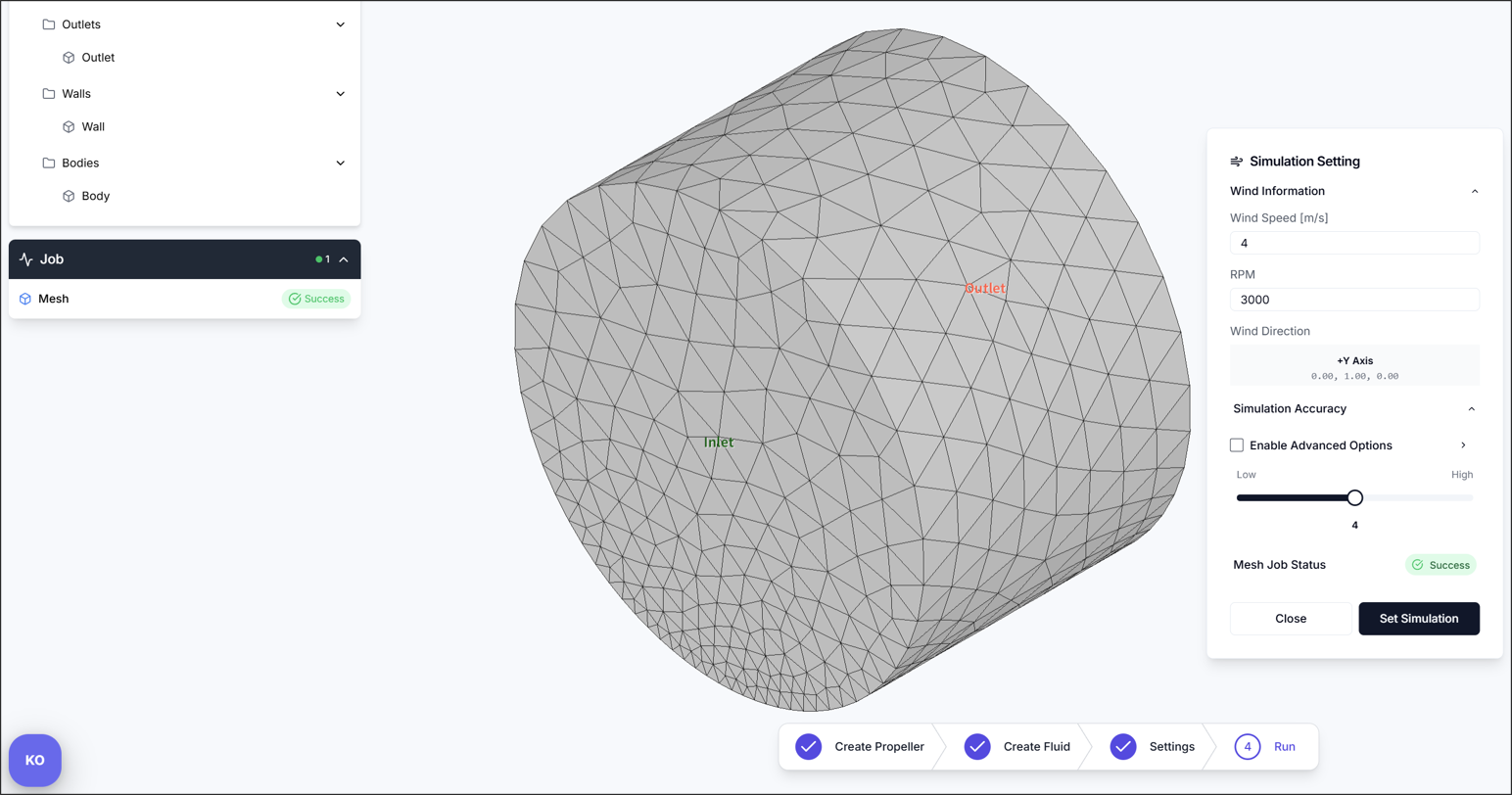
After a moment, verify that the mesh was generated correctly.
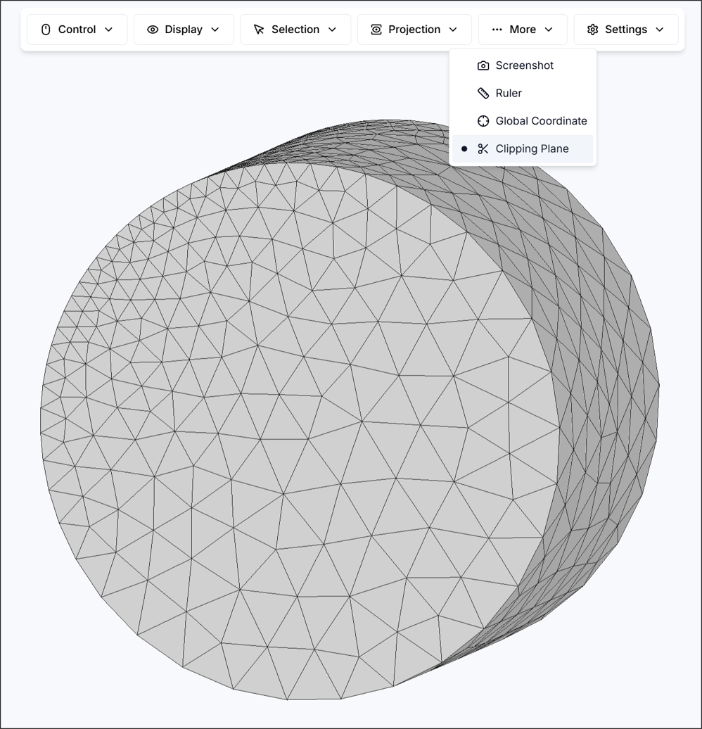
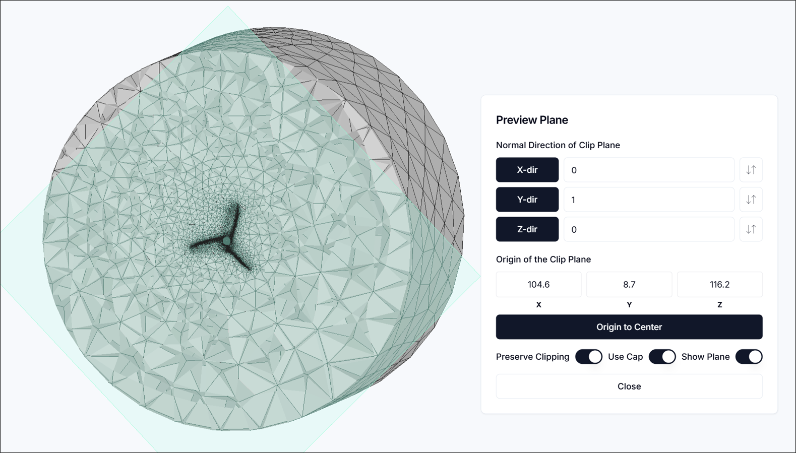
Tip: To check the quality of the generated mesh, it's recommended to use the More > Clipping Plane feature. You can view the internal mesh structure in cross-section to verify proper mesh generation.
4. Run Simulation
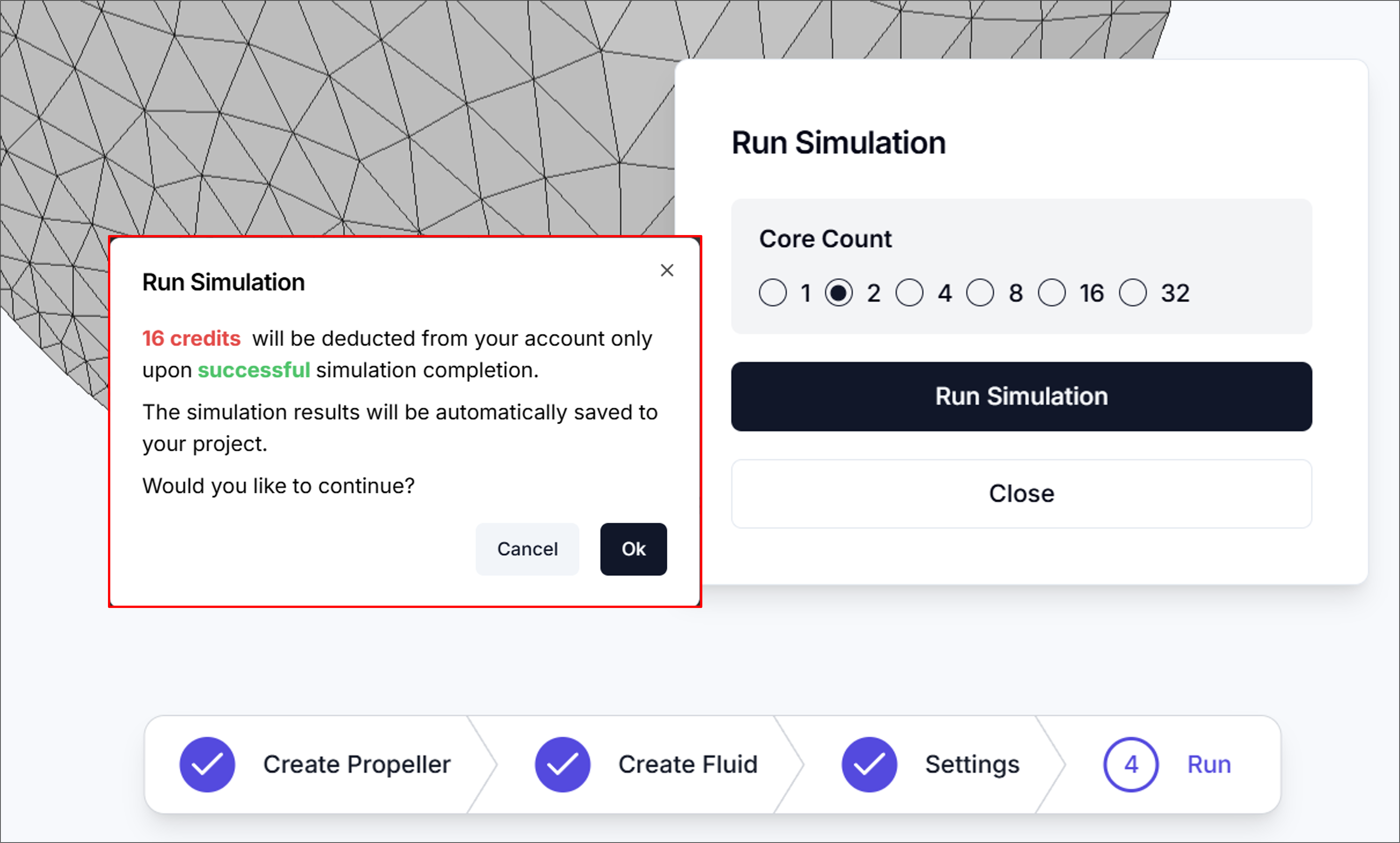
Core Count: Specifies the number of computational nodes (cores) to use for the simulation. Generally, more nodes result in faster computation, but credits are consumed proportionally to the number of nodes used.
5. Residuals
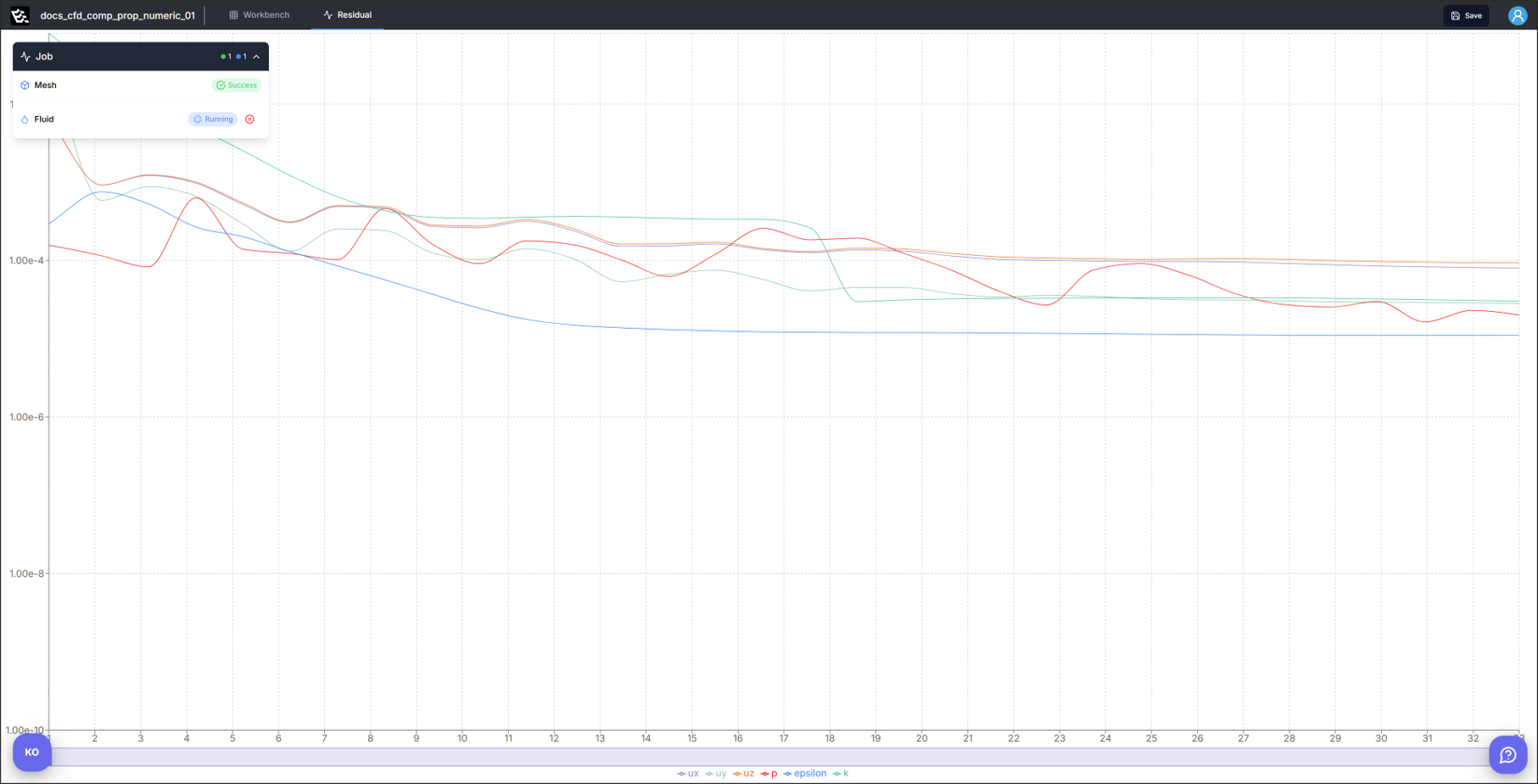
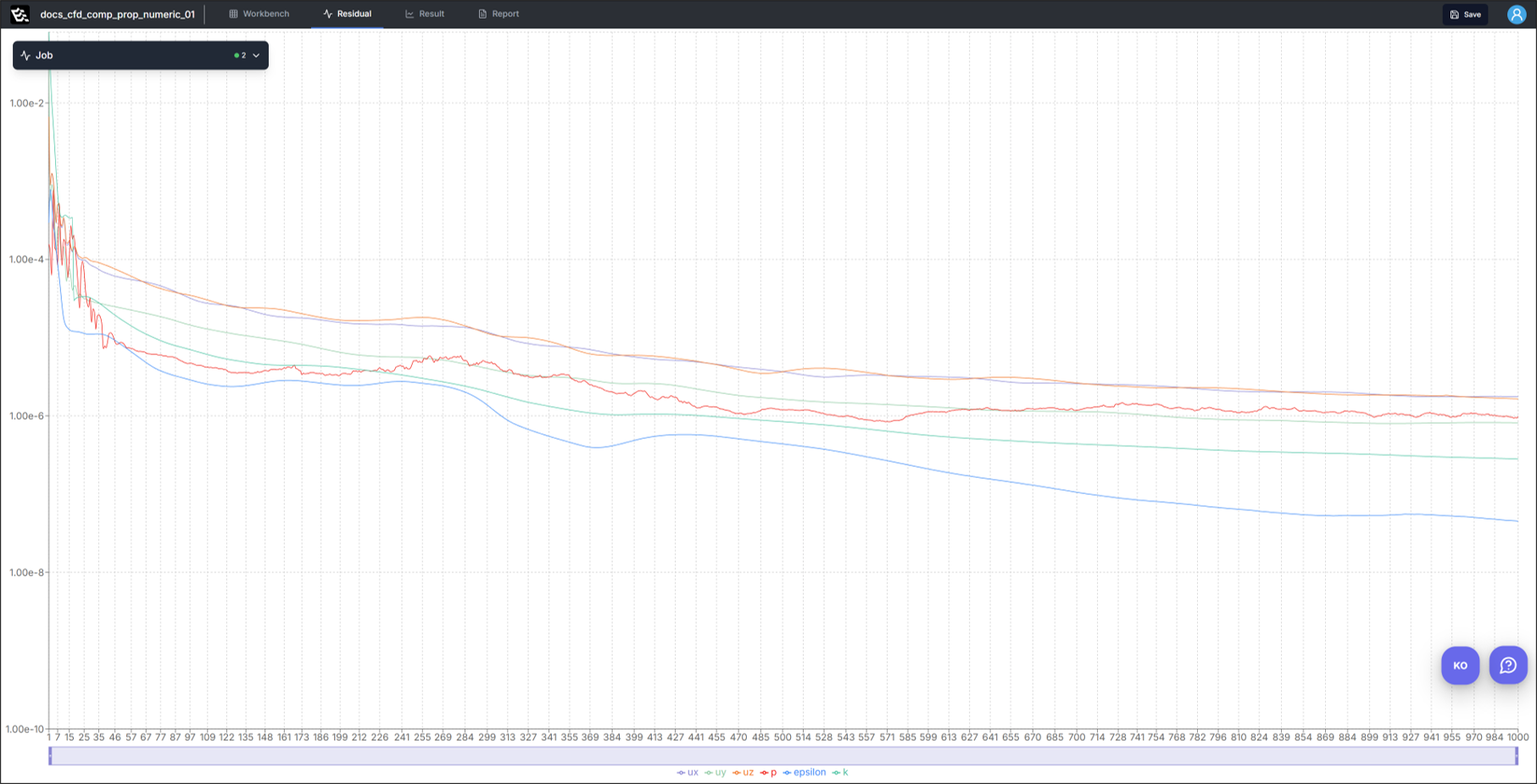
When you run the simulation, you can monitor the simulation progress or completion status in the Residual panel.
6. Results
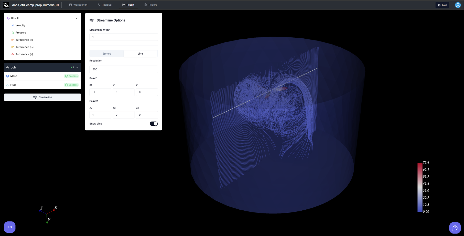
In the Results section, you can visualize Velocity, Pressure, and various Turbulence terms as 3D contours.
For the Velocity field, streamline visualization is also supported.
7. Report
In this section, you can evaluate propeller performance based on numerical data calculated from simulation results.
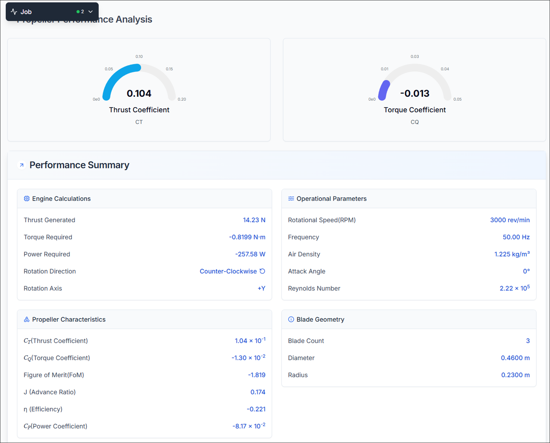
7.1. Propeller Performance Analysis
Displays dimensionless performance coefficients.
- Thrust Coefficient: Dimensionless thrust generated by the propeller
- Torque Coefficient: Dimensionless torque required for propeller rotation
7.2. Performance Summary
Summarizes key performance parameters.
7.2.1. Engine Calculations
- Thrust Generated: Total axial force (propulsive force) generated by the propeller
- Torque Required: Propeller shaft torque due to aerodynamic drag (used for motor selection)
- Power Required: Mechanical input power needed to overcome torque at given RPM (P=2πnQ)
- Rotation Direction: Direction of propeller rotation (CW/CCW), affects wake and swirl
- Rotation Axis: Direction of the rotation axis (e.g., +X, +Y, etc.)
7.2.2. Operating Parameters
- RPM: Propeller revolutions per minute, directly affects thrust and torque
- Frequency: Analysis time step frequency (related to numerical stability in unsteady analysis)
- Air Density: Assumed fluid density (default 1.225 [kg/m³])
- Angle of Attack: Angle between incoming flow and propeller disc normal (affects thrust generation)
- Reynolds Number: Dimensionless number based on blade chord and inflow conditions (determines flow characteristics)
7.2.3. Propeller Characteristics
- Figure of Merit (FoM): Ideal hover efficiency (used in rotorcraft analysis)
- Advance Ratio (J): Dimensionless number representing the relationship between forward velocity and propeller rotation speed
- Efficiency (η): Propulsive efficiency indicating how well input power is converted to useful thrust
- Power Coefficient (Cp): Normalized input power value
7.2.4. Blade Geometry
- Blade Count: Number of propeller blades (affects loading and efficiency)
- Diameter/Radius: Actual size of the propeller (used in all dimensionless calculations)
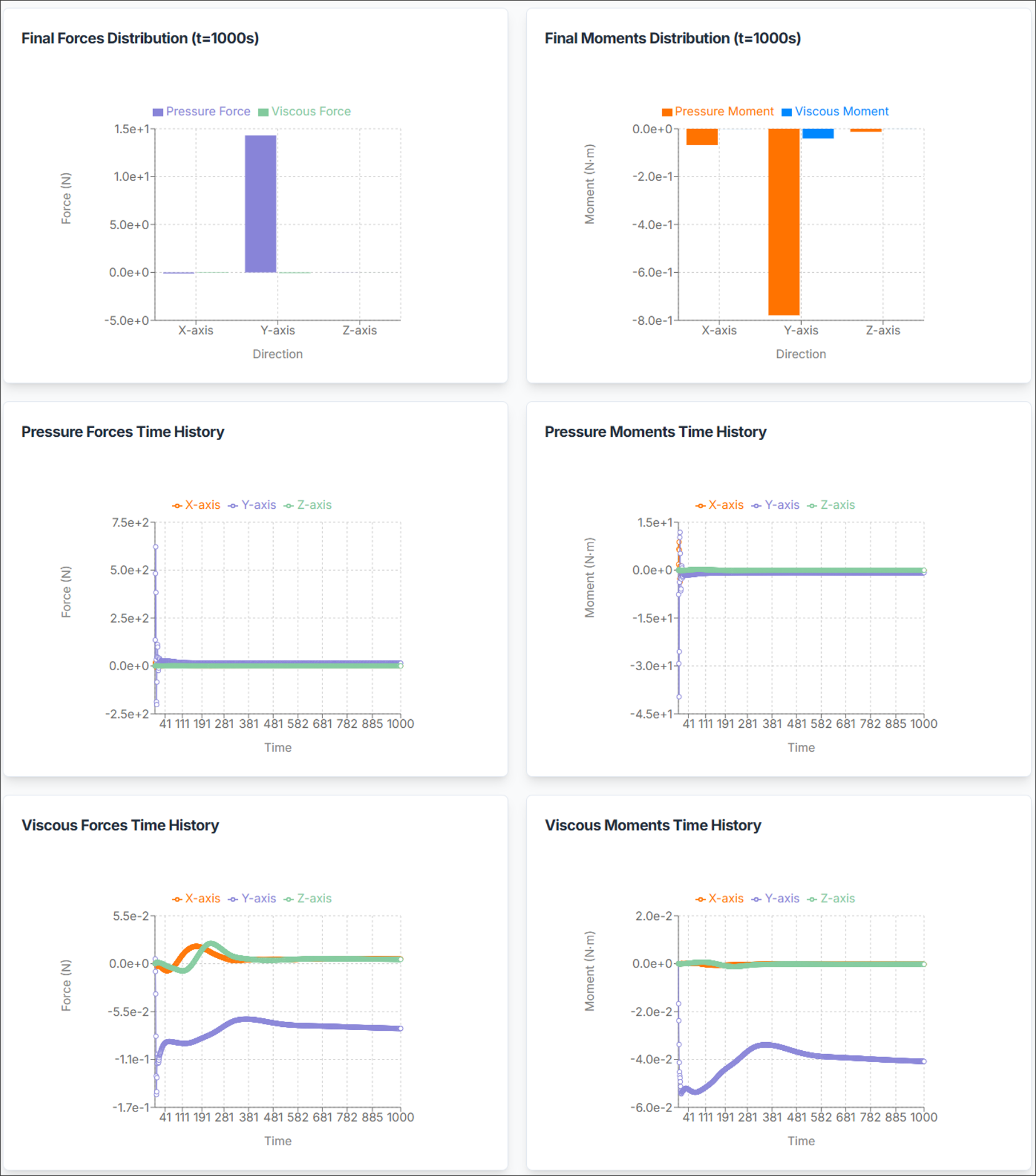
7.3. Force and Moment Distribution
Displays total aerodynamic forces and moments broken down as follows:
- Pressure Forces: Surface forces due to static and dynamic pressure distribution
- Viscous Forces: Forces due to shear stress and fluid viscosity
- Pressure Moments: Torque due to pressure distribution on blade surfaces
- Viscous Moments: Torque due to viscous (shear) effects (generally smaller than pressure moments)
Each term is decomposed into X, Y, Z components for evaluating symmetry, imbalance, and axial loads.
7.4. Time History
Provides graphs of force and moment variations over time.
- Verify convergence in unsteady analysis
- Detect oscillations/instabilities and determine if steady state has been reached
Need Assistance or Have Questions?
Frequently Asked Questions: FAQ Link
Support Inquiries: support@everysim.io