4.3 Structural Analysis: Integration-Aircraft
The Integration-Aircraft feature in Structural Analysis has the same functionality as Integration-Custom.
1. Import CAD
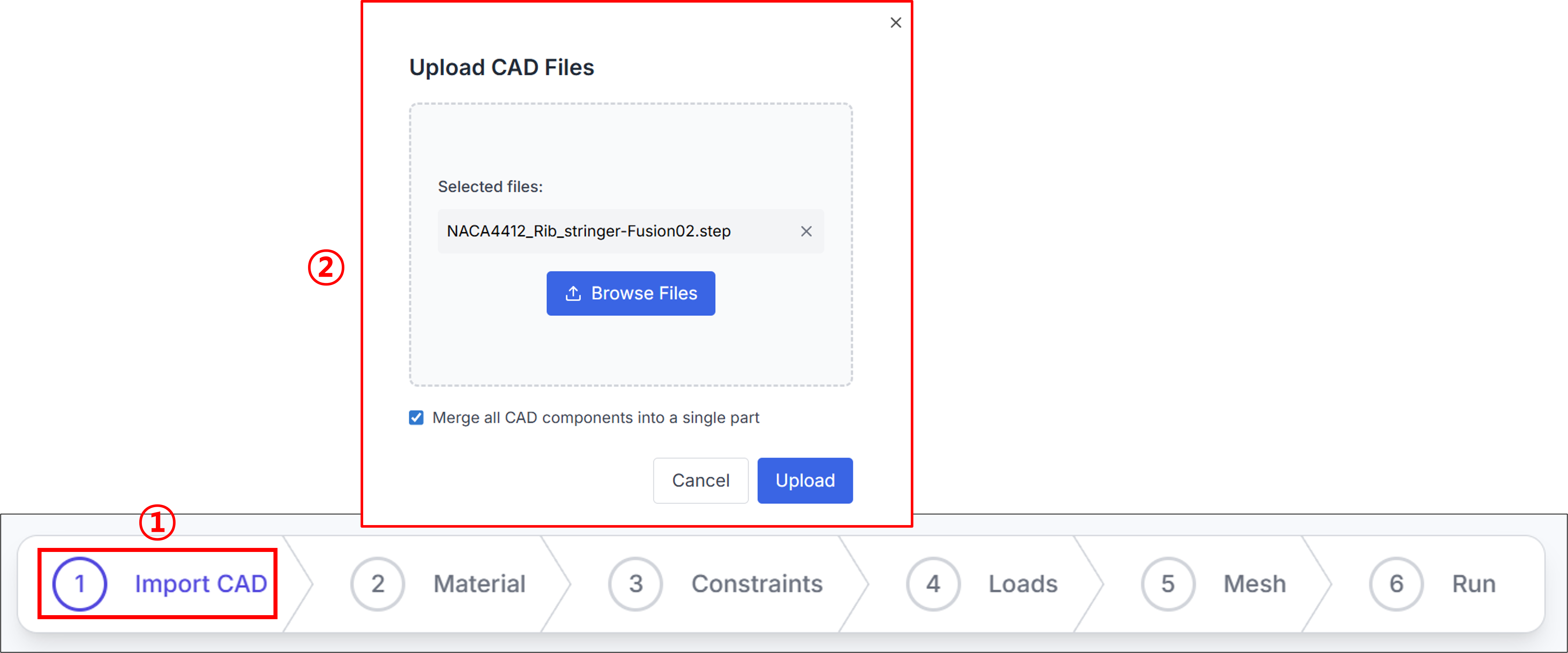
You can import external CAD files to create an aircraft. If you have a CAD file, you can select and import it using the Browse Files button.
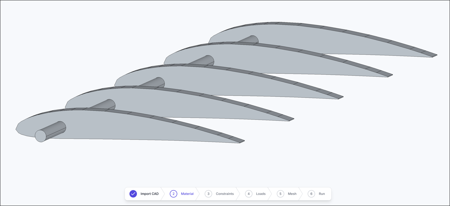
If the import is successful, the imported CAD geometry will be displayed on screen.
2. Assign Material
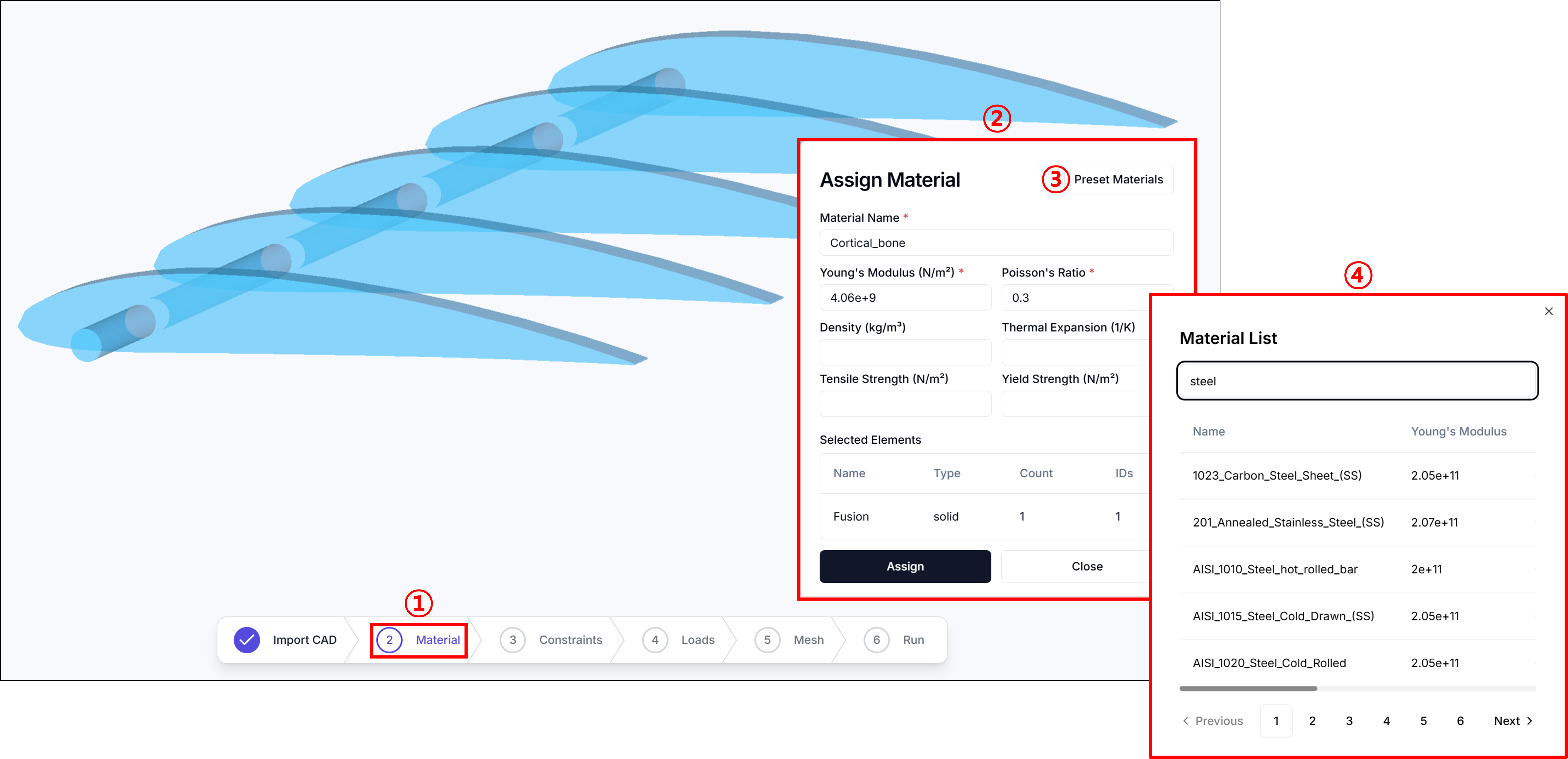
Material assignment can be done by selecting Material in step 1. To use materials from the library, select Preset Materials as shown in step 3, then search for the desired material name in step 4 and select Assign to apply it.
3. Constraints
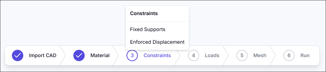
In the Constraints section, you can set Fixed Supports and Enforced Displacement.
3.1. Fixed Support
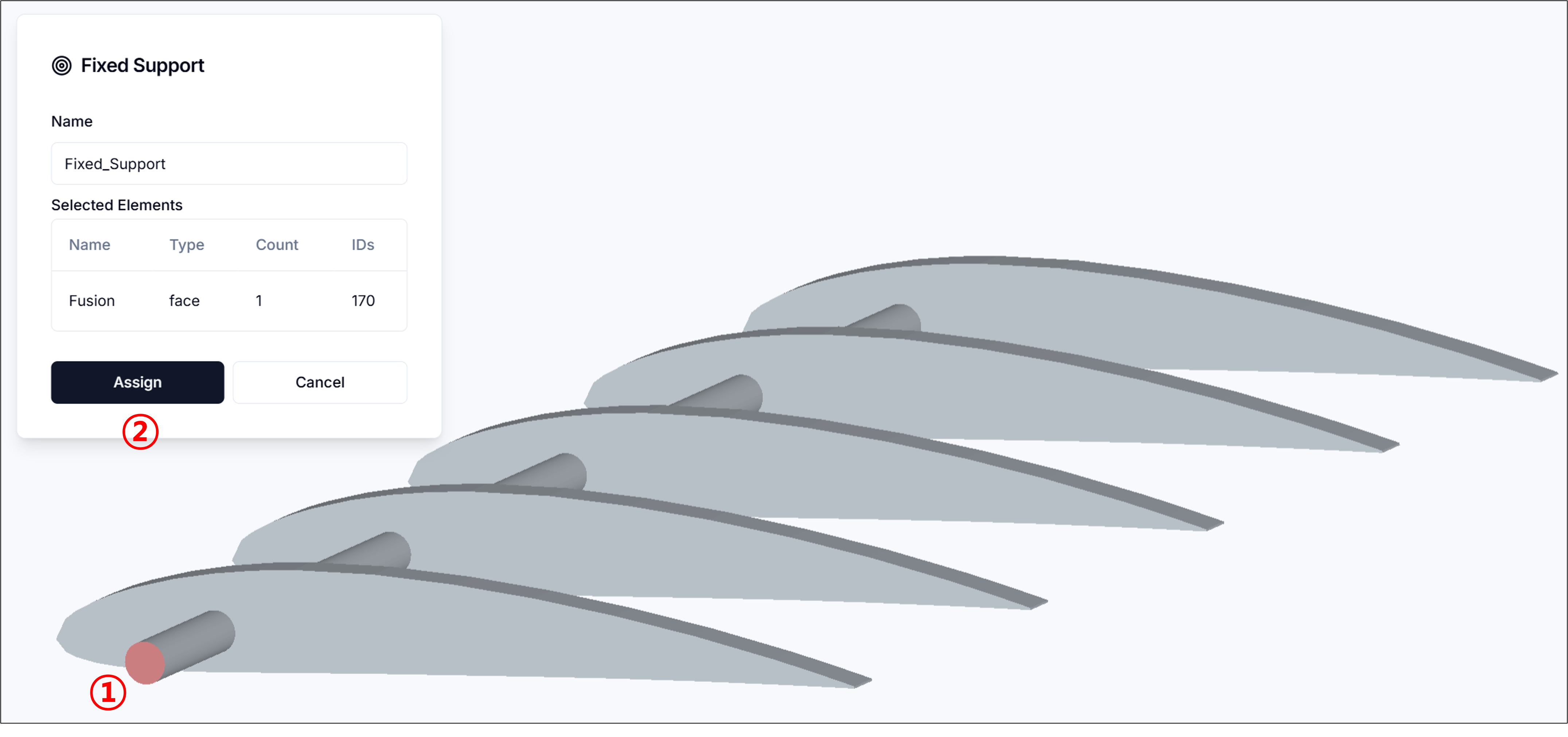
Fixed Support is used to constrain selected surfaces. You can select surfaces with a left mouse click, and hold Shift to select multiple surfaces simultaneously. After selecting all surfaces, click Assign to complete the fixed support setting.
3.2. Enforced Displacement
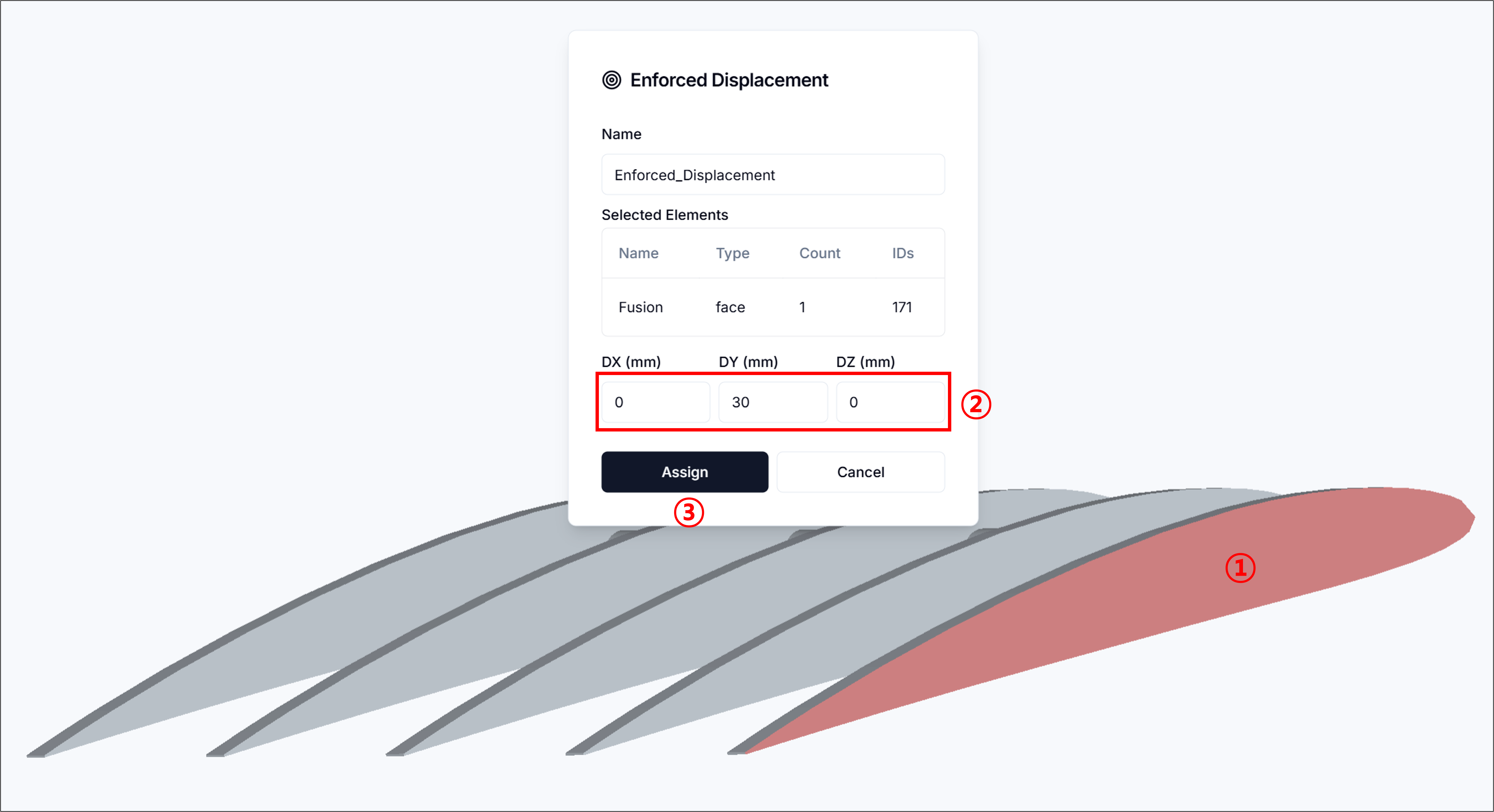
Enforced Displacement is used to apply displacement to selected surfaces. You can select surfaces with a left mouse click, and use Shift to select multiple surfaces. After selecting surfaces, enter the displacement values and click Assign to complete the enforced displacement setting.
4. Loads
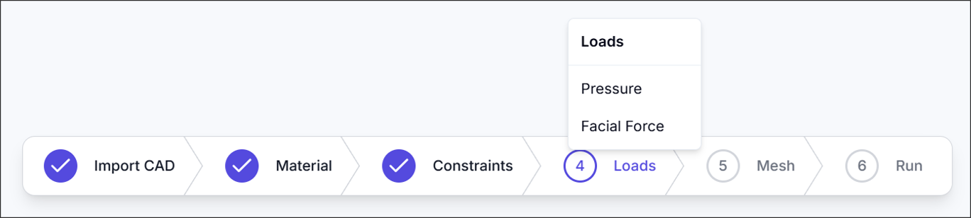
In the Loads section, you can set Pressure and Facial Force.
4.1. Pressure
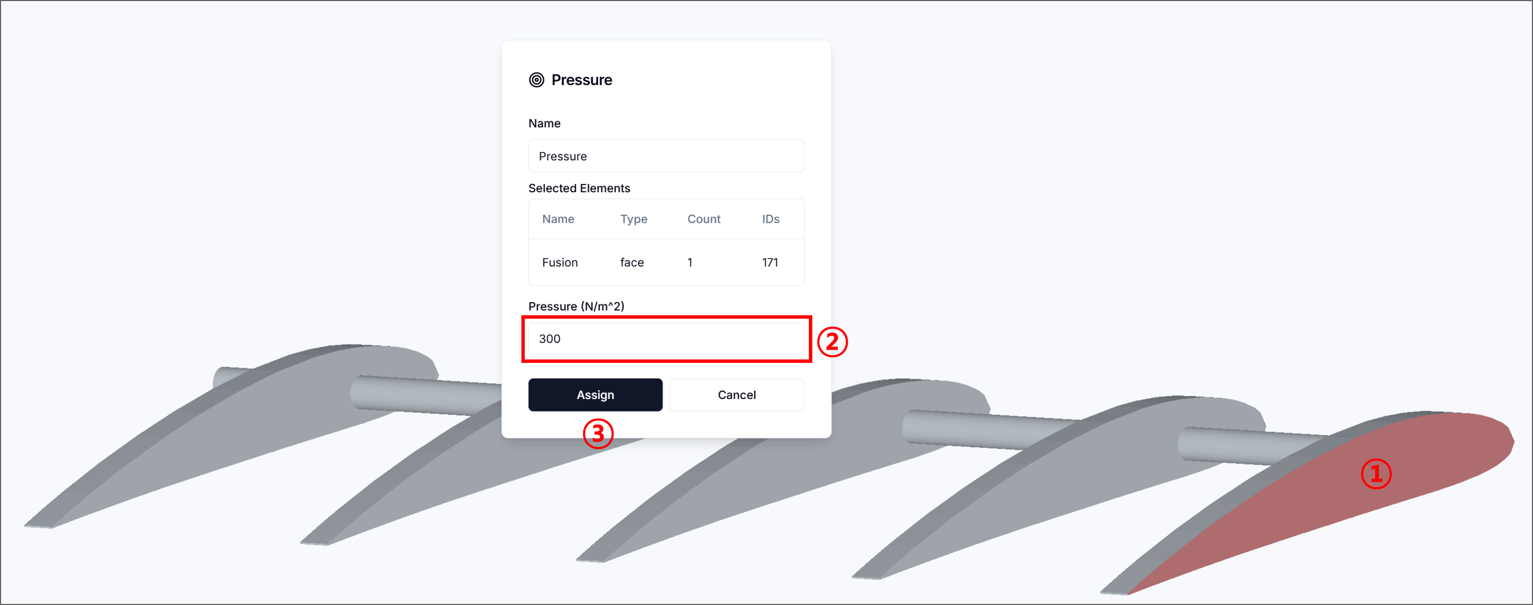
Pressure is used to apply force perpendicular to selected surfaces. You can select surfaces with a left mouse click, and use Shift to select multiple surfaces. After selecting surfaces, enter the pressure value and click Assign to complete the pressure setting.
4.2. Facial Force
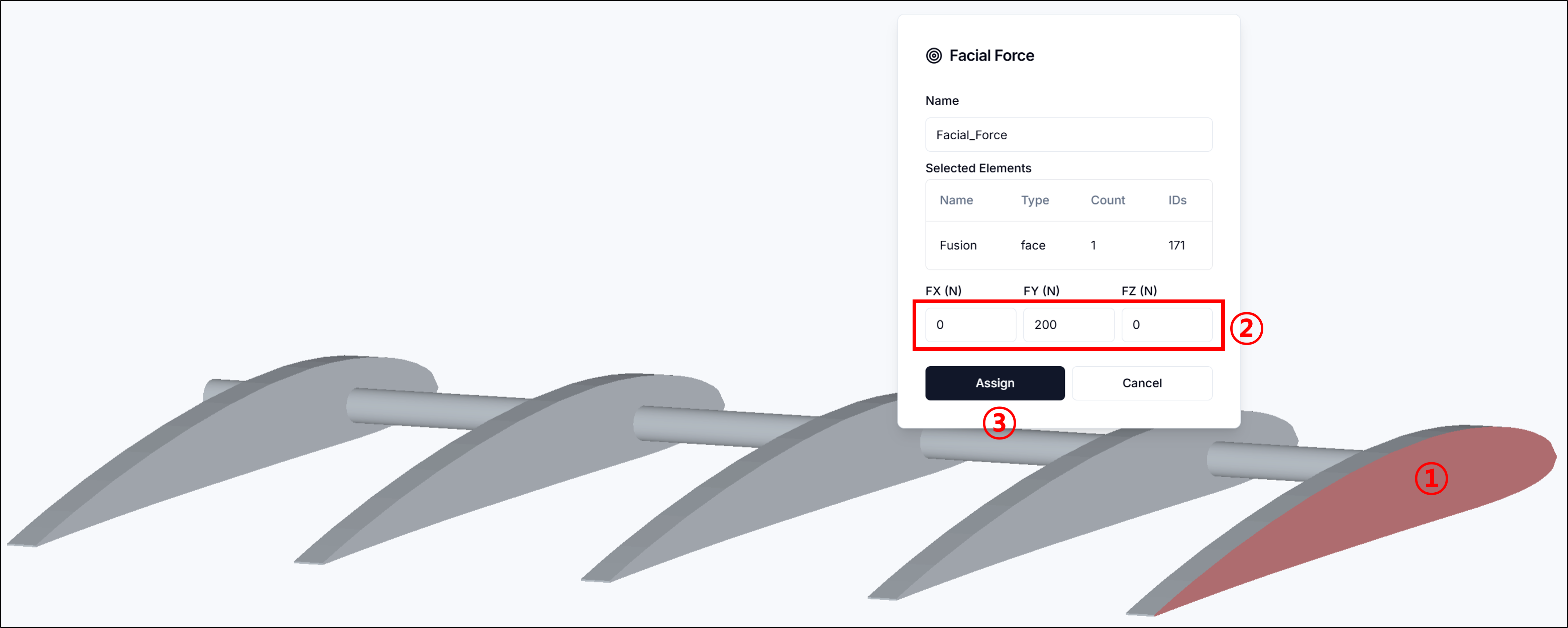
Facial Force is used to apply force in an arbitrary direction (3 axes) to selected surfaces. You can select surfaces with a left mouse click, and use Shift to select multiple surfaces. After selecting surfaces, enter the facial force values and click Assign to complete the facial force setting.
5. Mesh Setup
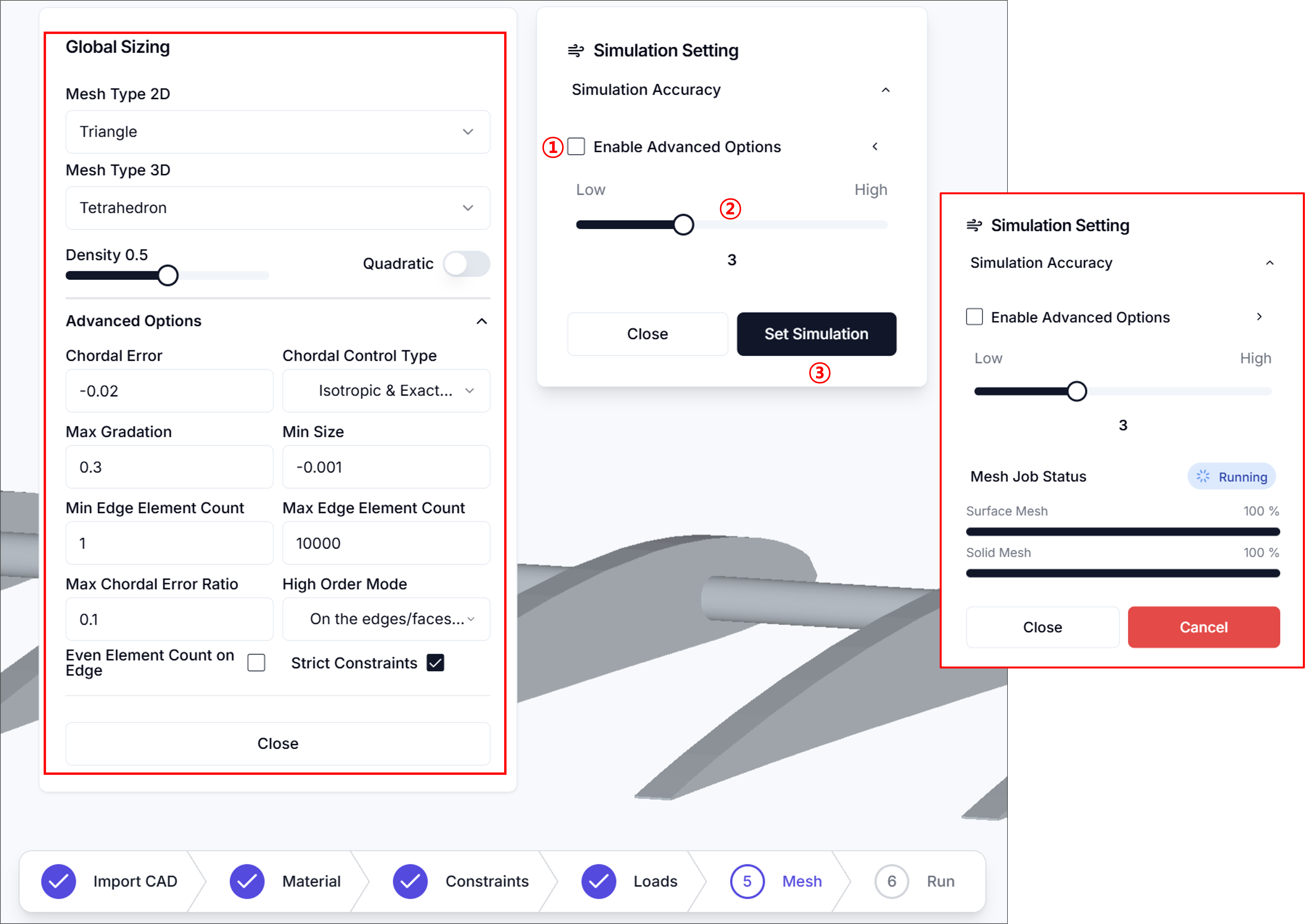
5.1. Simulation Accuracy
- Sets mesh density and refinement level.
- Enabling advanced options allows detailed mesh configuration.
5.2. Mesh Parameters (Advanced Options)
-
2D Mesh Type
- Select surface mesh type applied to faces
- Triangle
- QuadDominant
- Quadrangle
- Select surface mesh type applied to faces
-
3D Mesh Type
- Select volume mesh type applied inside the fluid region
- Tetrahedron
- HexaDominant
- Hexahedron
- Select volume mesh type applied inside the fluid region
-
Density
- Adjust overall mesh density with a slider (higher values create finer meshes)
-
Chordal Error
- Maximum allowable deviation between mesh edges and actual geometry (lower values improve geometric fidelity)
-
Chordal Control Type
- Select how chordal error is applied
- No Curvature
- Isotropic & Approximate Curvature
- Anisotropic & Approximate Curvature
- Isotropic & Exact Curvature
- Anisotropic & Exact Curvature
- Select how chordal error is applied
-
Max Gradation
- Maximum size ratio between adjacent elements (controls mesh transition smoothness)
-
Min Size
- Minimum edge length for generated mesh elements
-
Min Edge Element Count
- Minimum number of elements per edge
-
Max Edge Element Count
- Maximum number of elements per edge
-
Max Chordal Error Ratio
- Maximum ratio between actual chordal error and target value
-
High Order Mode
- High-order treatment method for curved surfaces
- Interpolated
- On the edges/faces but not equidistant
- On the edges/faces but equidistant
- High-order treatment method for curved surfaces
-
Even Element Count on Edge
- Force even element count on edges for symmetry or periodicity (when needed)
After completing all settings, click Set Simulation to proceed with mesh generation.
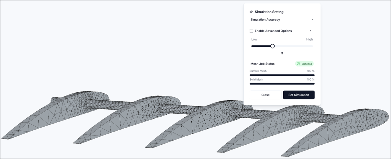
If the mesh is generated successfully, a success message will be displayed and the mesh will appear on screen.
6. Run Simulation
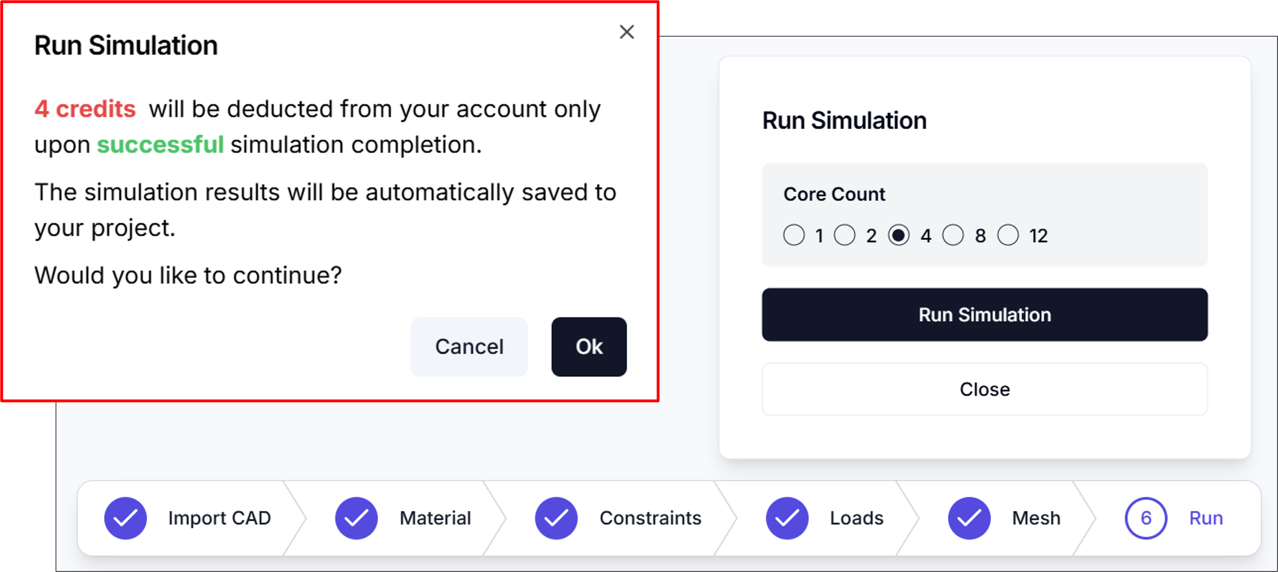
Core Count: You can specify the number of computational nodes to use for the simulation. More nodes result in faster computation, but credits are consumed proportionally to the number of nodes used.
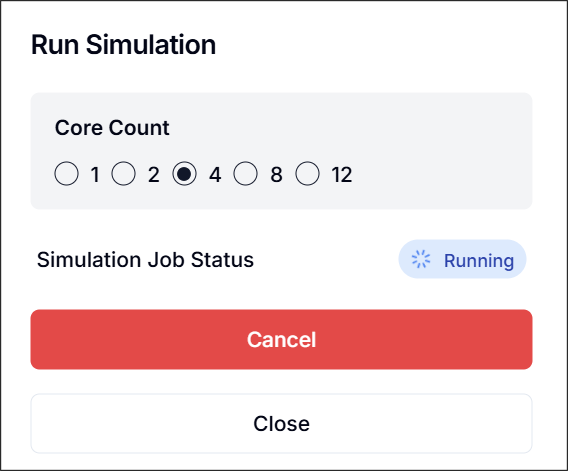
When you click Run Simulation, the status will change to Running.
7. Results
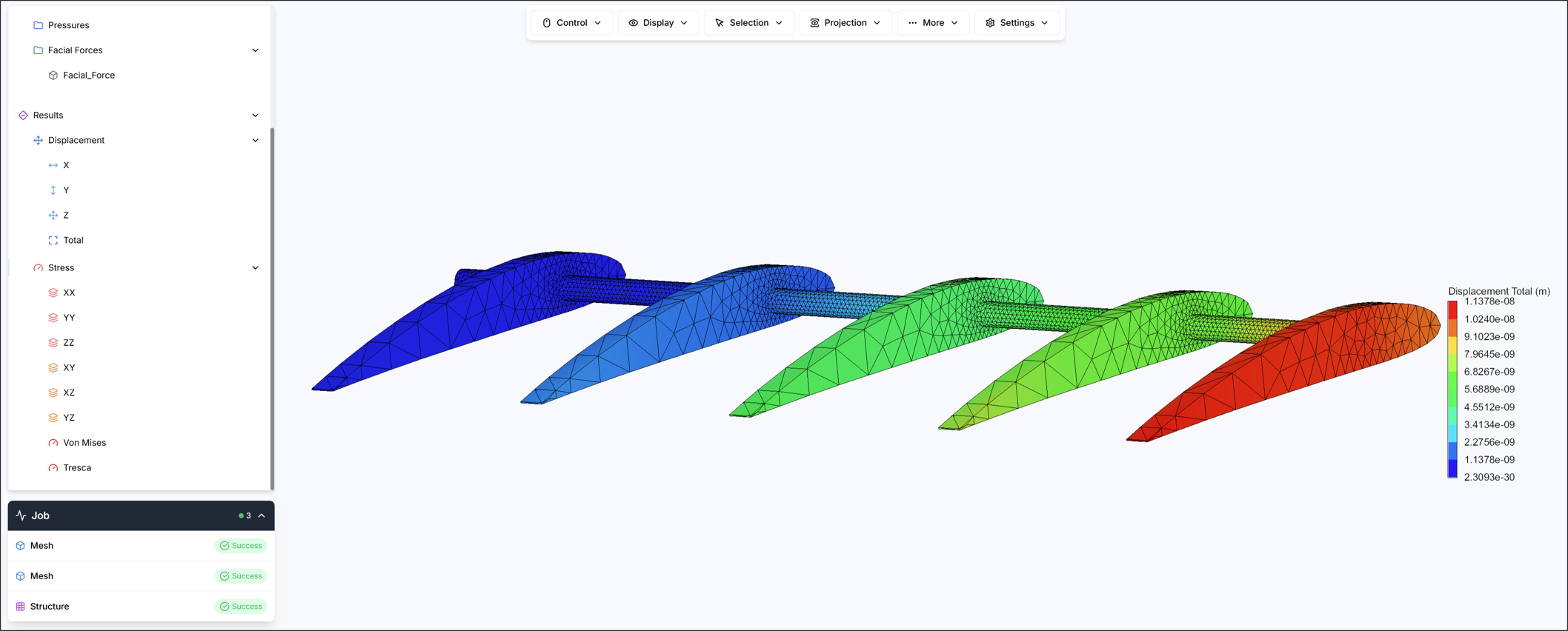
When the simulation is completed successfully, a results tree will be displayed and you can view the results.
Three types of results are provided on this screen.
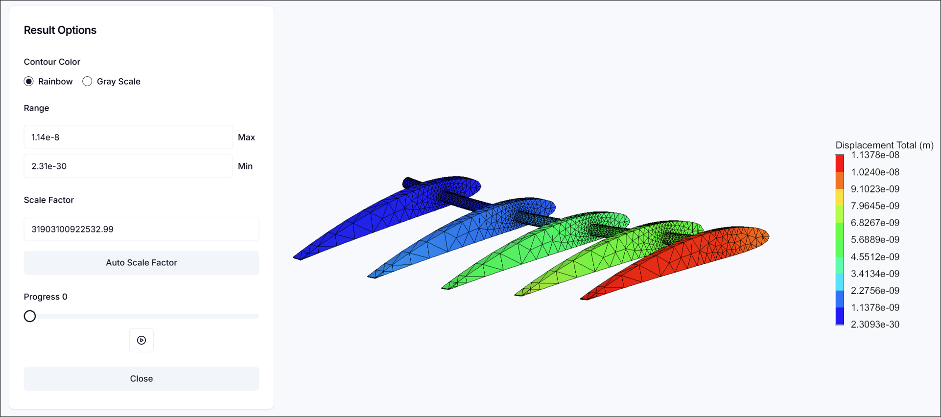
- Displacement: Shows actual displacement values.
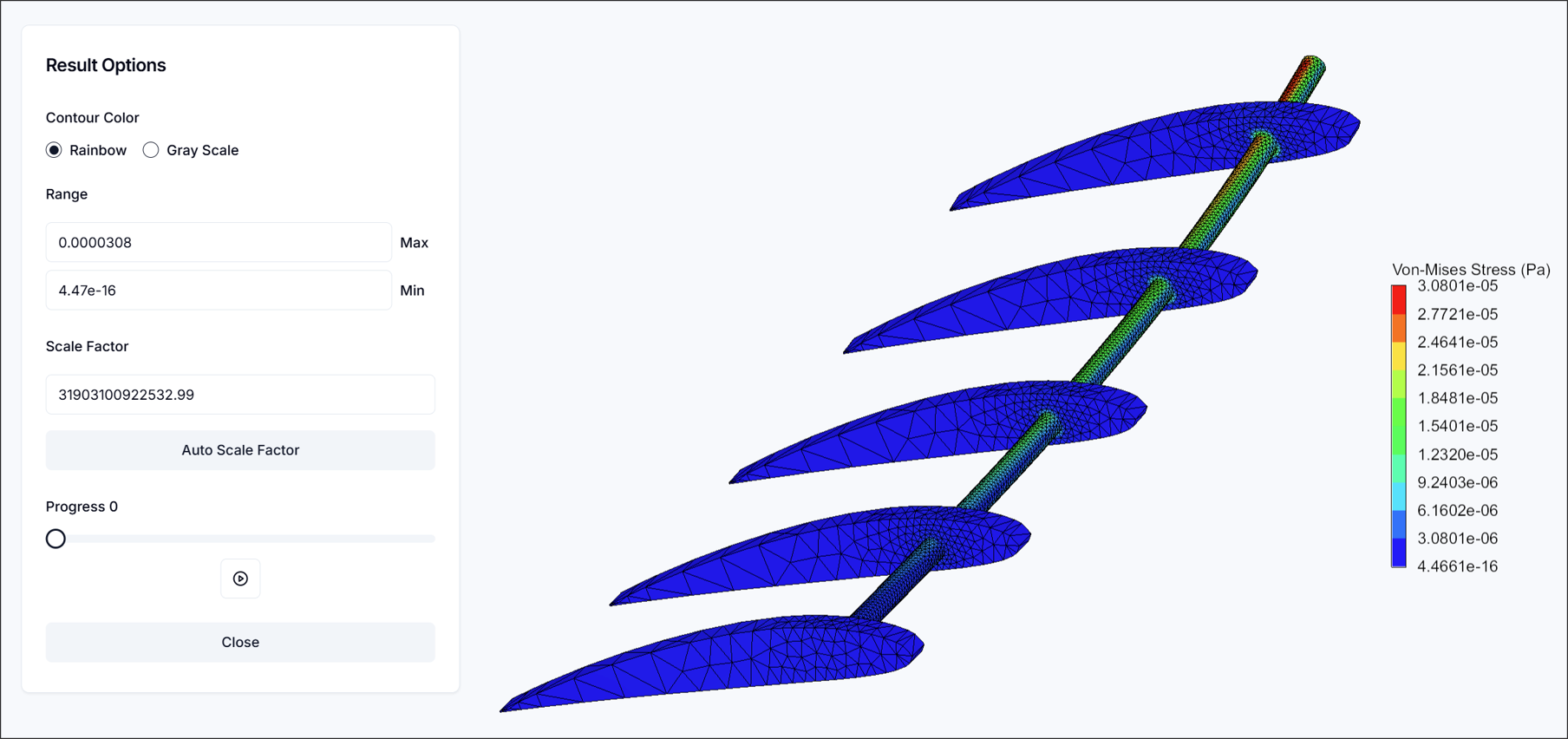
- Von Mises Stress: Assumes that yielding occurs when deformation energy (an element of strain energy) reaches a critical value. Commonly used to predict yielding by comparing with yield stress.
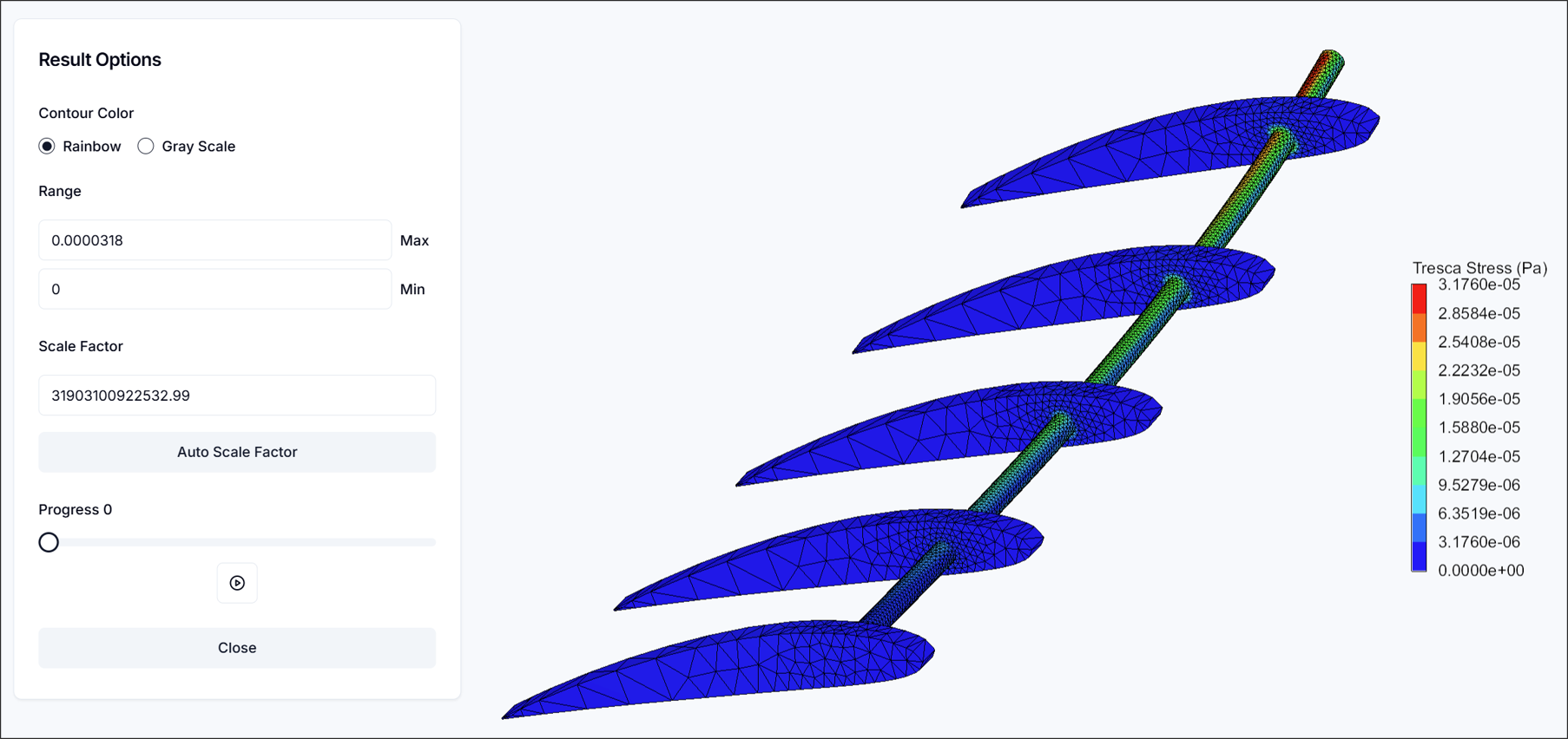
- Tresca Stress: Assumes that yielding occurs due to maximum shear stress. Generally provides more conservative results than Von-Mises stress.
Need Assistance or Have Questions?
Frequently Asked Questions: FAQ Link
Support Inquiries: support@everysim.io