4.7 Fluid Dynamics: Integration-Aircraft
The Integration-Aircraft feature in Fluid Dynamics has the same functionality as Integration-Custom.
1. Import CAD
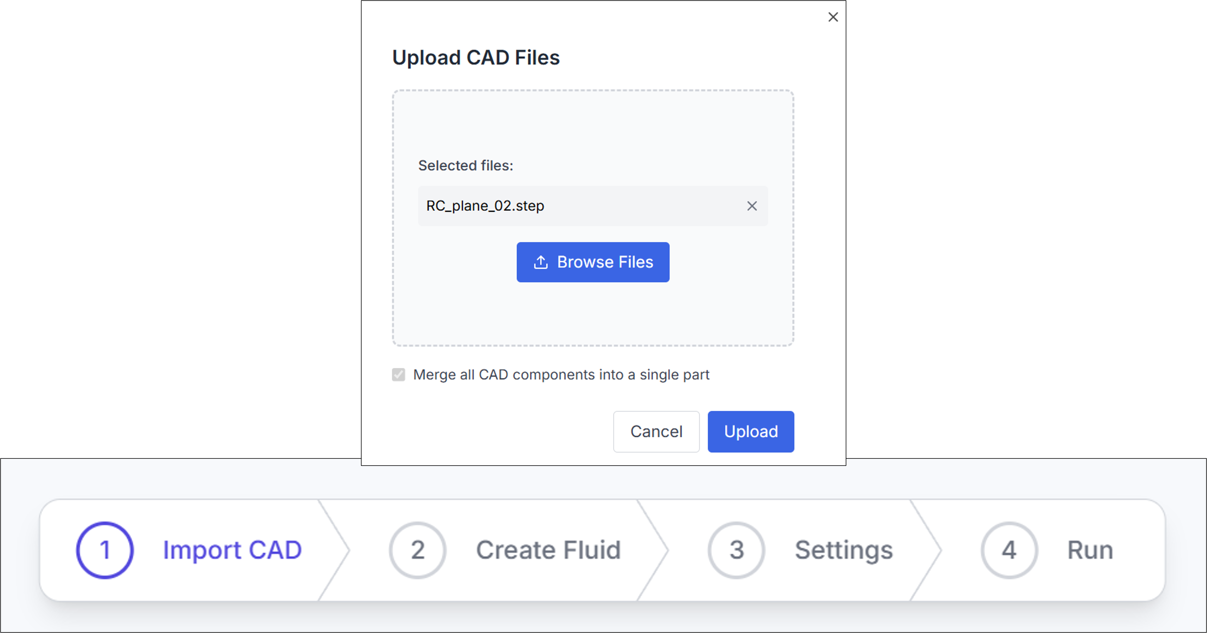
For the Integration-Custom process, it is assumed that you have a CAD file with .step extension prepared.
Use the Browse Files button to select and upload your desired file.
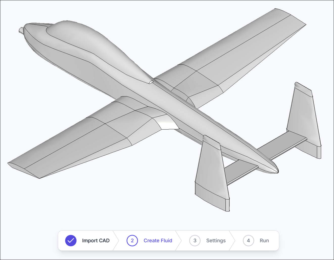
After the upload is complete, verify that the CAD file was recognized correctly.
2. Create Fluid Region
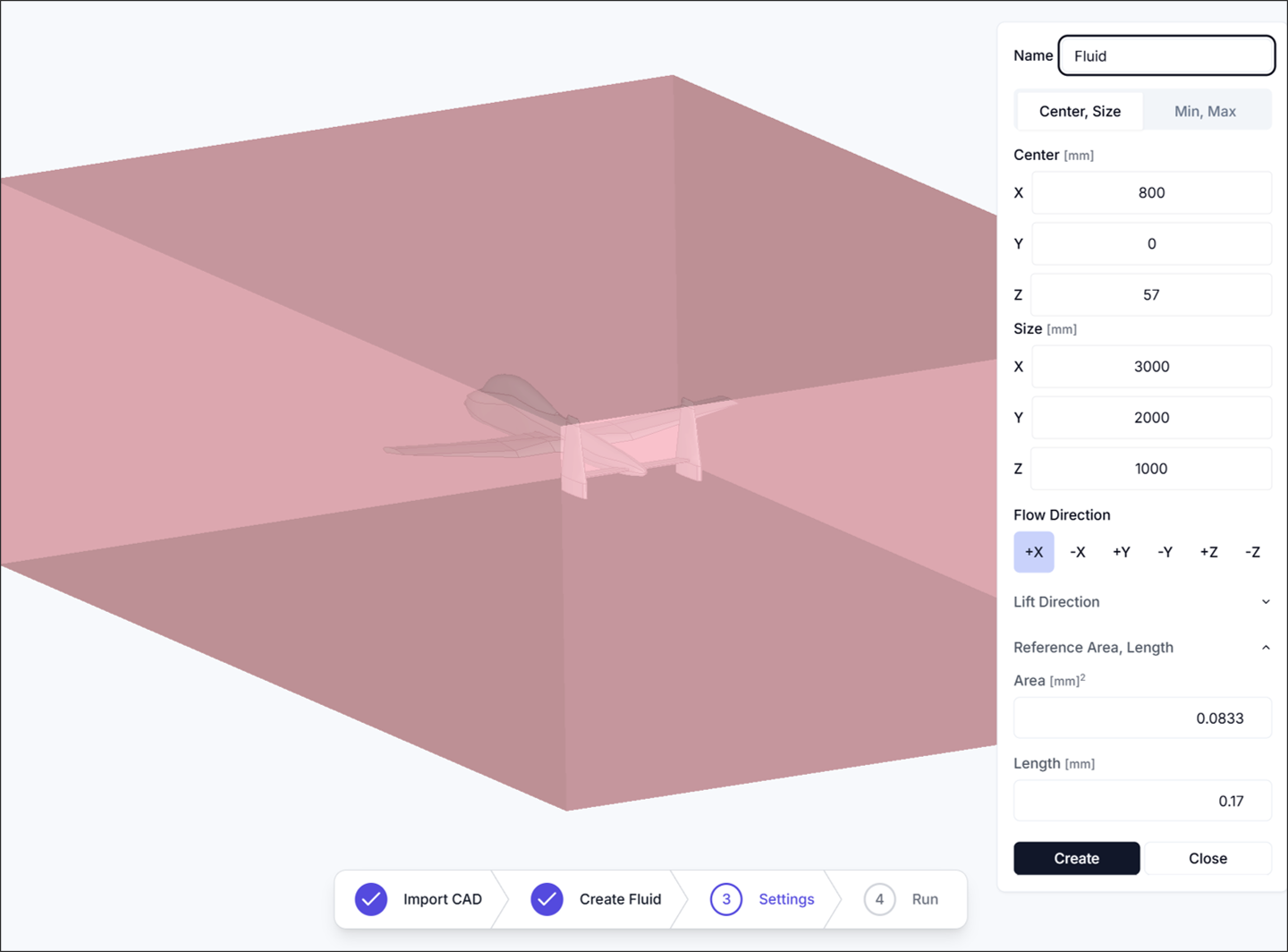
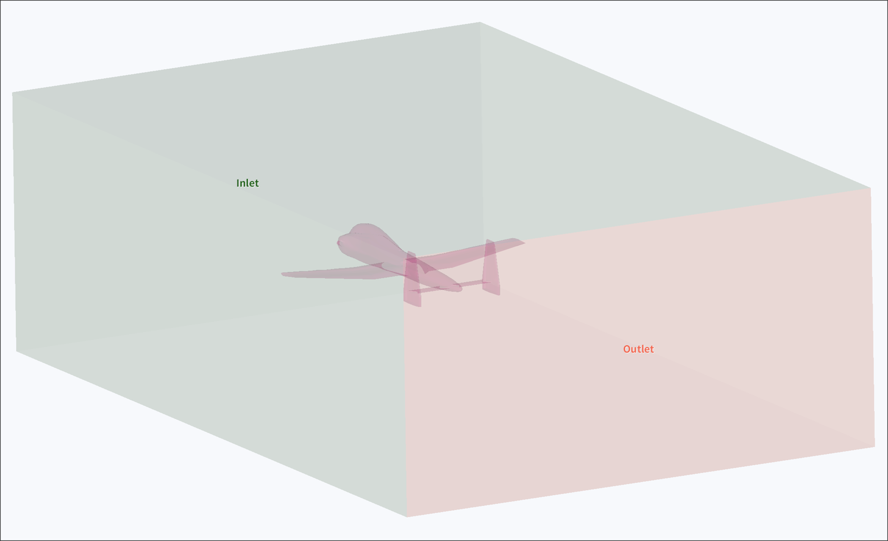
In the Create Fluid Region step, you define the fluid region for the simulation. When setting the Flow Direction, the axis aligns with the aircraft's forward direction, but the actual flow direction is set opposite to represent incoming flow.
- Center: Set the center of the fluid region as
<x, y, z>. - Size: Set the size of the fluid region as
<x, y, z>. - Flow Direction: Specify the direction of incoming flow.
- Lift Direction: Specify the lift direction, typically perpendicular to the upper surface of the main wing.
- Reference Area: Specify the reference area, commonly the planform area of the main wing.
- Reference Length: Specify the reference length, typically the Mean Aerodynamic Chord (MAC).
Mean Aerodynamic Chord (MAC): A reference length used when defining the characteristics of an aircraft wing.
After creating the fluid region, verify that it was generated correctly.
3. Simulation Settings
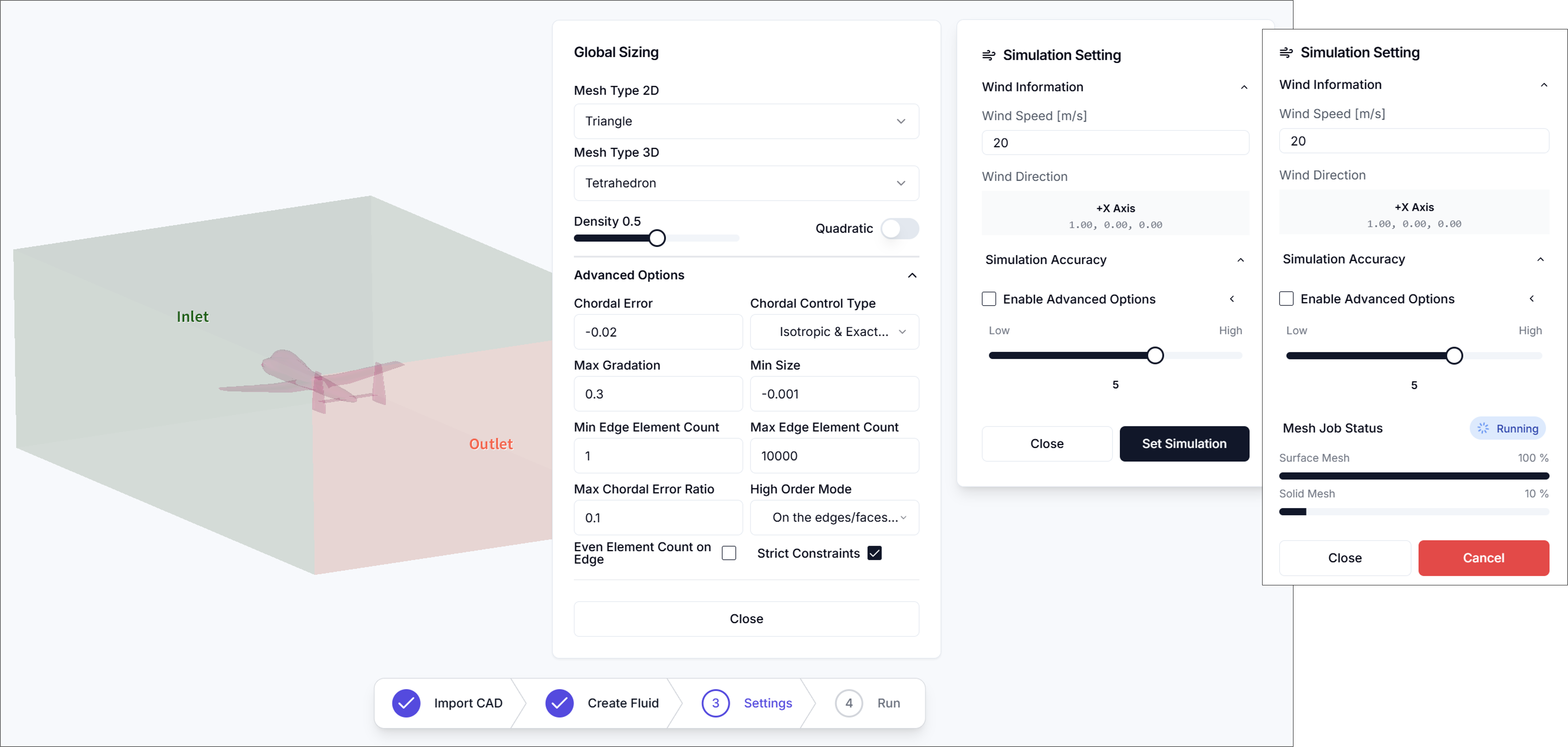
In the Simulation Settings step, you configure wind speed information and mesh generation settings.
3.1. Wind Speed Information
- Wind Speed [m/s]: Enter the aircraft's flight speed.
- Wind Direction: Shows the wind direction defined in the Create Fluid Region step.
3.2. Simulation Accuracy
Mesh resolution can be adjusted to the desired level. Detailed settings are as follows.
Mesh Parameters (Advanced Options)
-
2D Mesh Type
- Select surface mesh type applied to faces
- Triangle
- QuadDominant
- Quadrangle
- Select surface mesh type applied to faces
-
3D Mesh Type
- Select volume mesh type applied inside the fluid region
- Tetrahedron
- HexaDominant
- Hexahedron
- Select volume mesh type applied inside the fluid region
-
Density
- Adjust overall mesh density with a slider (higher values create finer meshes)
-
Chordal Error
- Maximum allowable deviation between mesh edges and actual geometry (lower values improve geometric fidelity)
-
Chordal Control Type
- Select how chordal error is applied
- No Curvature
- Isotropic & Approximate Curvature
- Anisotropic & Approximate Curvature
- Isotropic & Exact Curvature
- Anisotropic & Exact Curvature
- Select how chordal error is applied
-
Max Gradation
- Maximum size ratio between adjacent elements (controls mesh transition smoothness)
-
Min Size
- Minimum edge length for generated mesh elements
-
Min Edge Element Count
- Minimum number of elements per edge
-
Max Edge Element Count
- Maximum number of elements per edge
-
Max Chordal Error Ratio
- Maximum ratio between actual chordal error and target value
-
High Order Mode
- High-order treatment method for curved surfaces
- Interpolated
- On the edges/faces but not equidistant
- On the edges/faces but equidistant
- High-order treatment method for curved surfaces
-
Even Element Count on Edge
- Force even element count on edges for symmetry or periodicity (when needed)
After completing all settings, click Set Simulation to proceed with mesh generation.
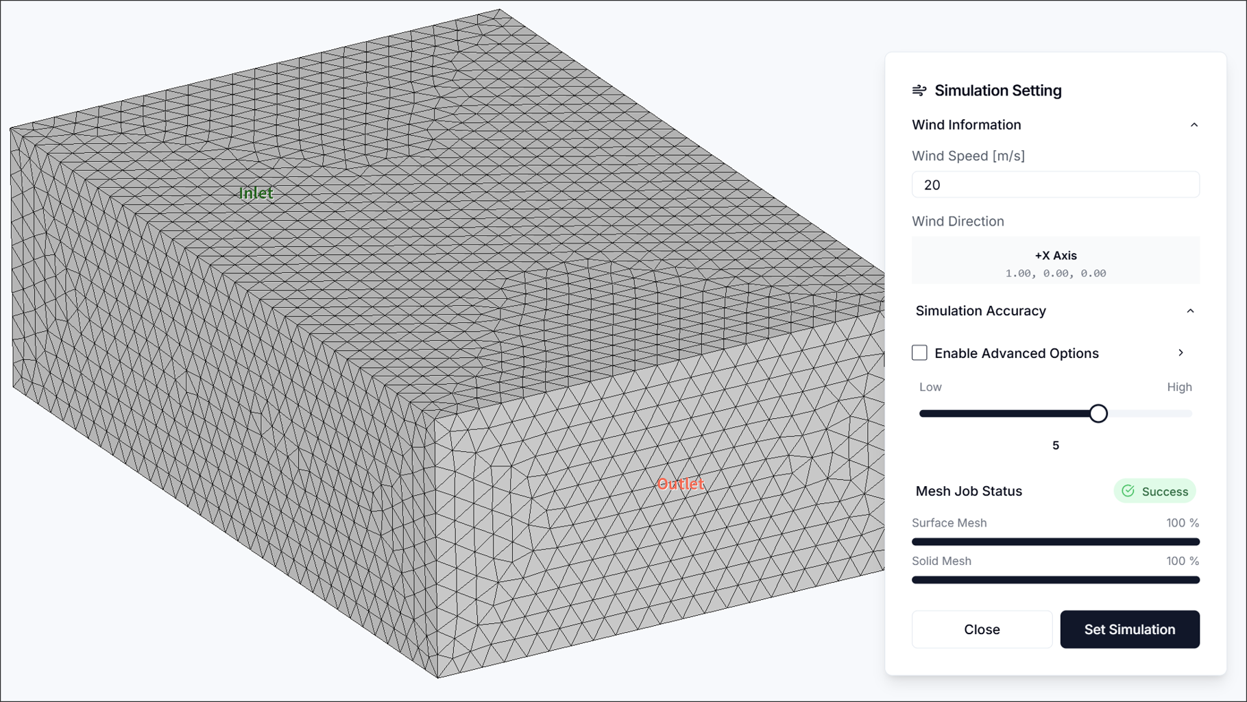
After simulation settings are complete, verify that the mesh was generated correctly.
4. Run Simulation
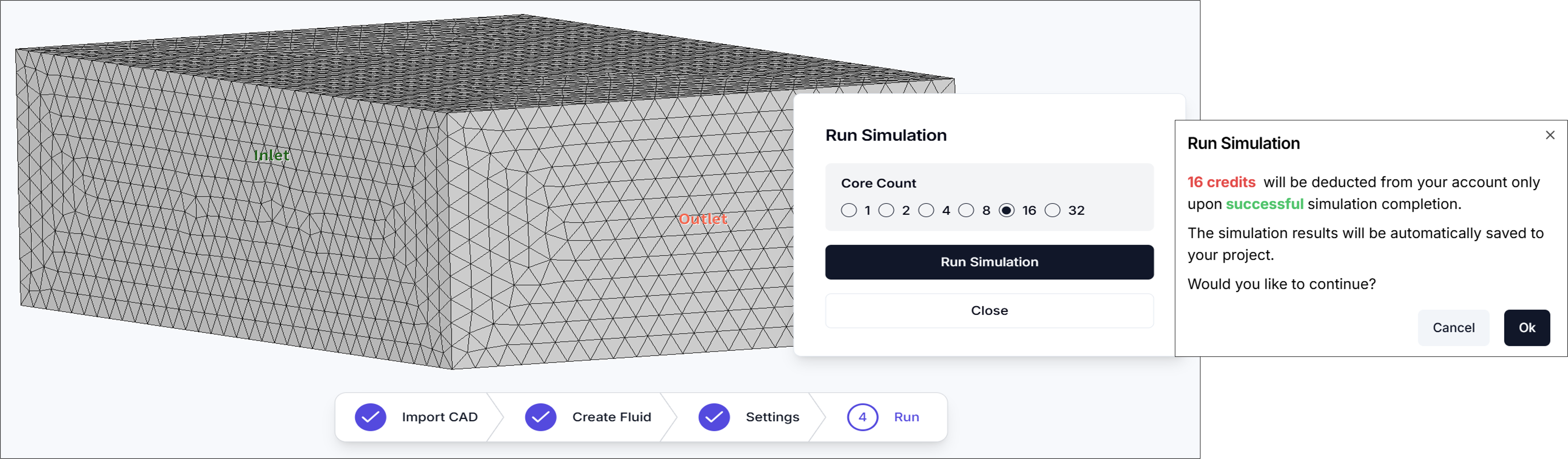
In the Run Simulation step, specify the Core Count and start the analysis. Generally, increasing the core count reduces simulation time, but more credits are consumed.
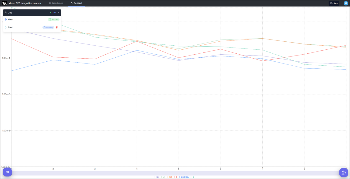
When the simulation starts successfully, the screen will automatically switch to the Residuals window.
Residuals
A fundamental metric for evaluating CFD solution convergence. To determine if the simulation has converged properly, residual values for each solution variable should be sufficiently low.
5. Results (3D Contour)
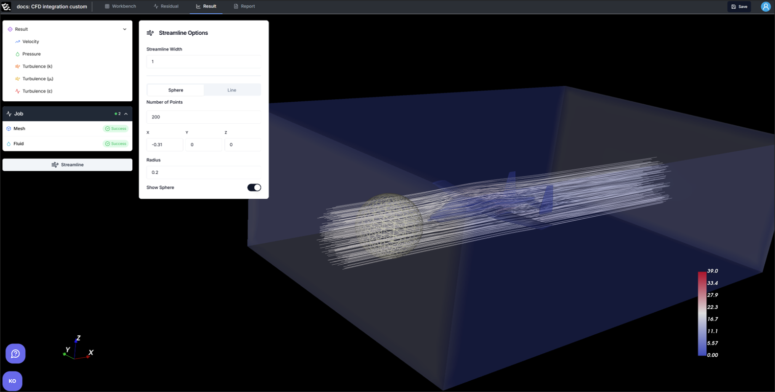
In the Results window, various physical quantities can be visualized.
- Velocity
- Streamlines: Streamline visualization is provided, with Sphere or Line methods available.
- Pressure
- Turbulence
6. Report
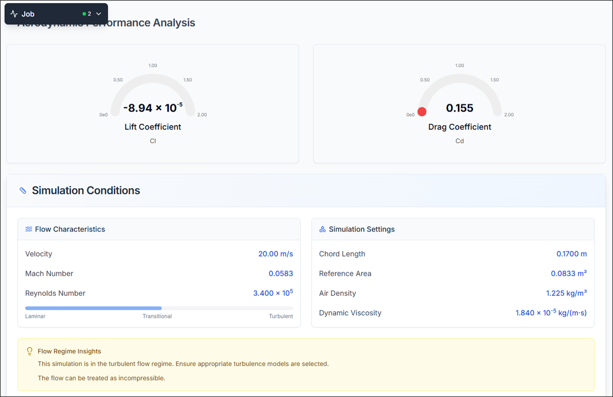
6.1. Aerodynamic Performance Analysis
Lift Coefficient (CL)
The Lift Coefficient is a dimensionless value representing the lift generated by an aircraft, defined as follows:
Where:
- : Lift
- : Air density (typically 1.225 kg/m³)
- : Wind speed
- : Reference area (e.g., wing planform area)
Drag Coefficient (CD)
The Drag Coefficient is a dimensionless value representing the drag acting on an aircraft, defined as follows:
Where:
- : Drag
- : Air density
- : Wind speed
- : Reference area (e.g., wing planform area)
Flow Characteristics
- Velocity: Same as wind speed
- Mach Number: Dimensionless number representing the ratio of object speed to speed of sound in the surrounding medium
- Reynolds Number: Dimensionless number representing the ratio of inertial forces to viscous forces in a fluid
Simulation Settings
- Chord Length: Same as Mean Aerodynamic Chord (MAC)
- Reference Area: Same as reference area defined in Create Fluid Region step
- Air Density: Typically assumed as 1.225 [kg/m³]
- Dynamic Viscosity: Degree of resistance to flow when external force is applied to a fluid
6.2. Force & Moment Distribution/Time History
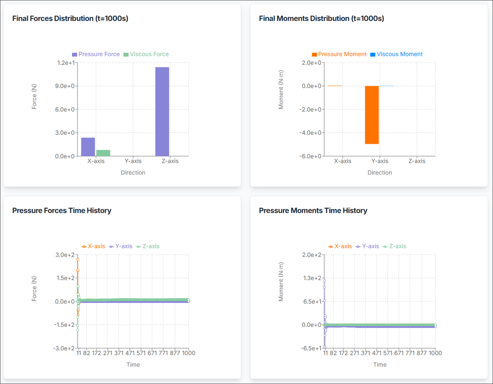
- Force/Moment Distribution: Shows force and moment distribution at simulation completion. Values are separated into Pressure and Viscous (Friction) components.
- Time History: Shows changes in forces and moments over simulation time. This allows verification of aerodynamic value convergence and temporal behavior.
Need Assistance or Have Questions?
Frequently Asked Questions: FAQ Link
Support Inquiries: support@everysim.io