4.4 Structural Analysis: Integration-Custom
The current Custom workflow uses the same workbench stages, controls, and analysis outputs as the Structural Aircraft workflow. Select or upload the geometry appropriate to your project, then follow the same detailed setup below.
1. Import CAD
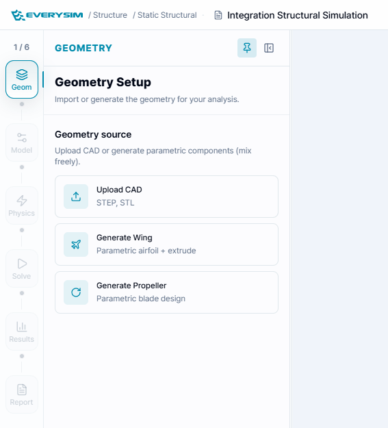
Users can create an aircraft by importing an external CAD file. If a CAD file is available, click Browse Files as shown in the figure to select and import the file.
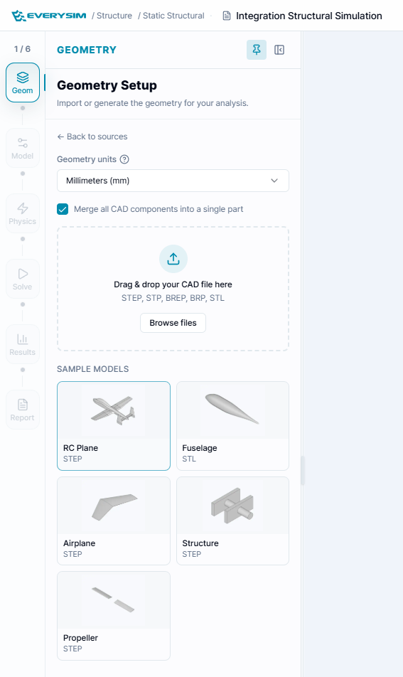
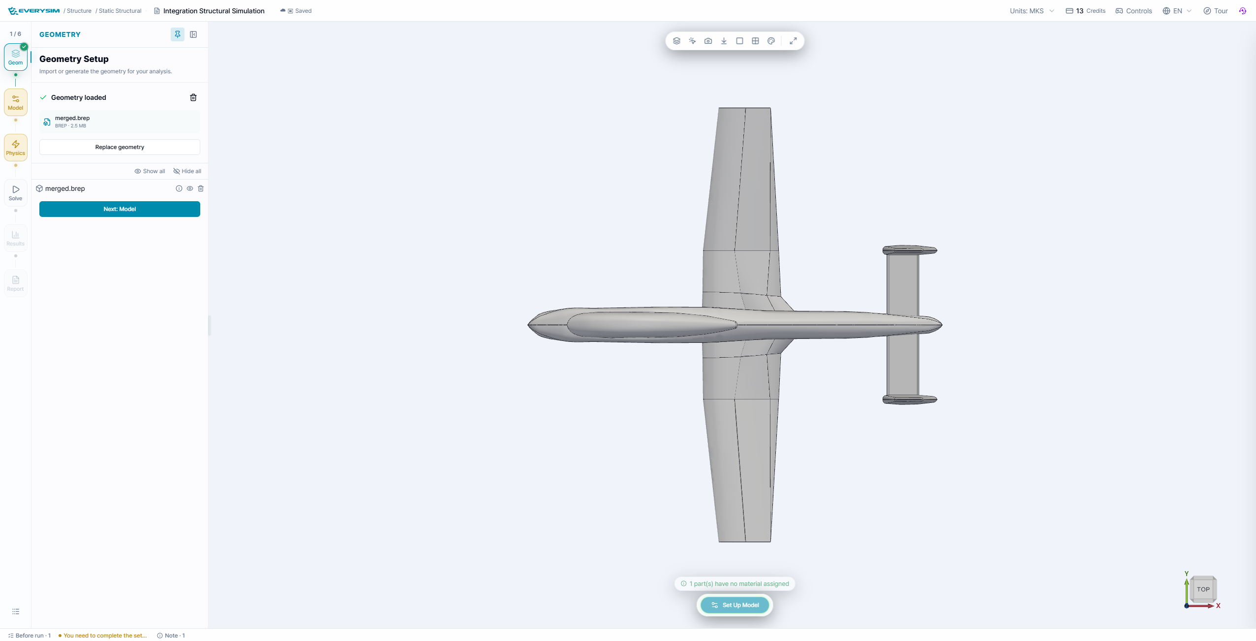
If the import is successful, the imported CAD geometry will be displayed as shown in the figure.
2. Assign Material
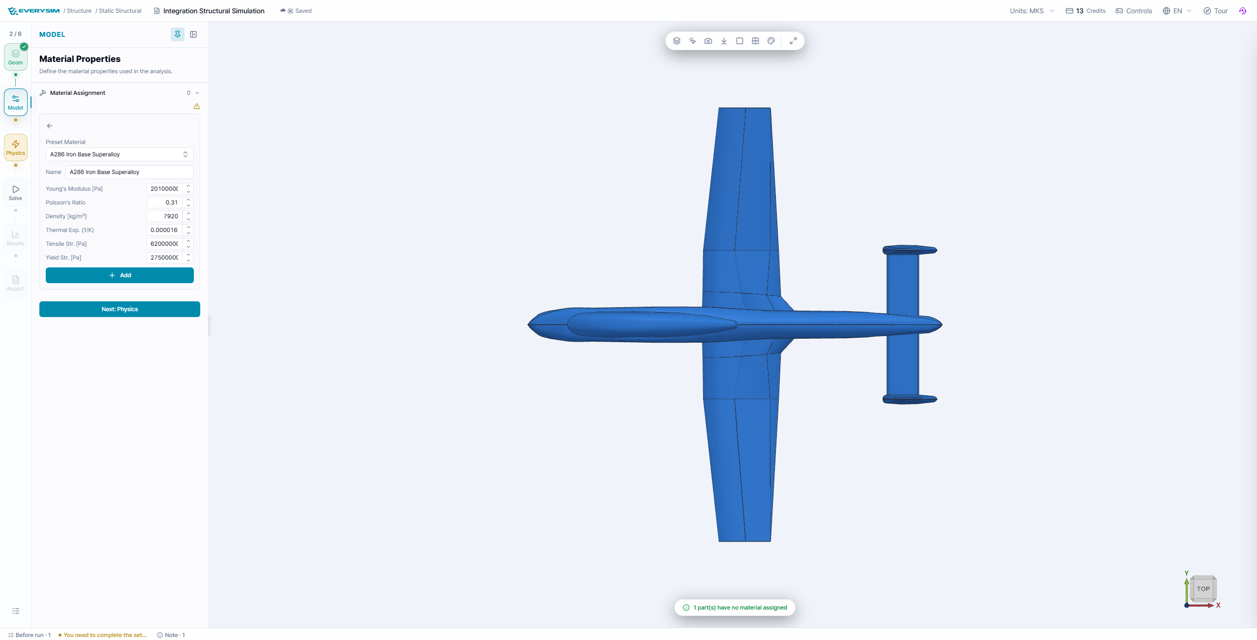
To set the material, click Material in Step 1 and configure the material properties.
If you want to use a material from the library, click Preset Materials at Step 3, enter the desired material name as shown in Step 4 to search for it, and then click Assign.
3. Constraints
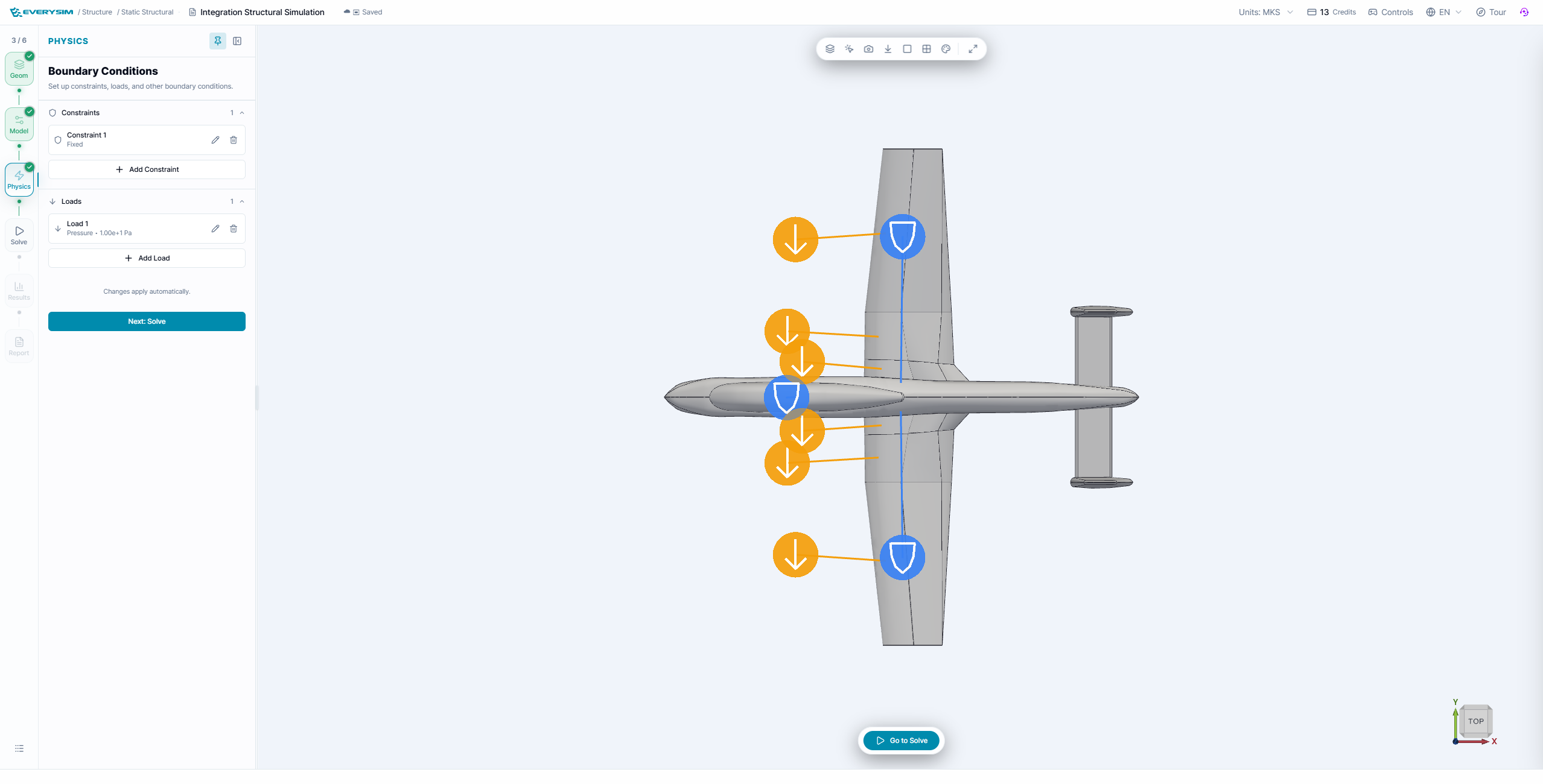
In the Constraints section, you can set Fixed Supports and Enforced Displacement.
The configuration methods for each are described below.
3.1. Fixed Support
Fixed Support: used to select the surfaces you want to constrain.
As shown in Step 1 of the figure, you can select a surface to fix by left-clicking with the mouse. Holding down Shift allows you to select multiple surfaces.
Once all desired surfaces are selected, click Assign as shown in Step 2 to complete the fixed support setup.
3.2. Enforced Displacement
Enforced Displacement: used to select the surfaces where displacement is to be applied.
As shown in Step 1 of the figure, select the target surfaces by left-clicking with the mouse. Holding down Shift allows you to select multiple surfaces.
After selecting all intended surfaces, enter the displacement value as shown in Step 2, then click Assign in Step 3 to complete the enforced displacement setup.
4. Loads
In the Load section, you can set Pressure and Facial Force.
The configuration methods for each are described below.
4.1. Pressure
Pressure: used when applying a force perpendicular to the selected surface.
As shown in Step 1 of the figure, select the target surfaces by left-clicking with the mouse. Holding down Shift allows you to select multiple surfaces.
After selecting all intended surfaces, enter the Pressure as shown in Step 2, then click Assign in Step 3 to complete the Pressure setup.
4.2. Facial Force
Facial Force: used to apply a force in arbitrary directions along the three axes on the selected surface.
As shown in Step 1 of the figure, select the target surfaces by left-clicking with the mouse. Holding down Shift allows you to select multiple surfaces.
After selecting all intended surfaces, enter the Facial Force as shown in Step 2, then click Assign in Step 3 to complete the facial force setup.
5. Mesh
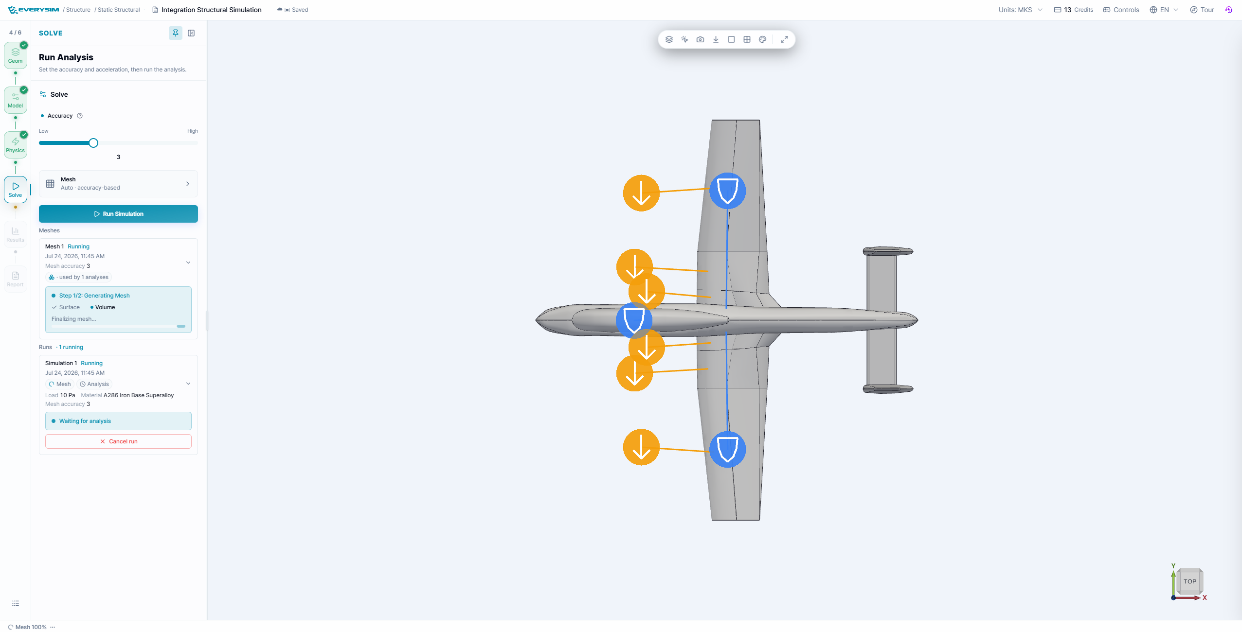
5.1. Simulation Accuracy
- Configures mesh density and refinement level for the simulation as shown in Step 2.
5.2. Meshing Parameters (Advanced Options)
-
Enable Advanced Options: Enables access to detailed meshing configuration.
-
Mesh Type 2D
Selects the type of surface mesh applied to faces.
- Triangle
- QuadDominant
- Quadrangle
-
Mesh Type 3D
Selects the type of volume mesh used within the fluid domain.
- Tetrahedron
- HexaDominant
- Hexahedron
-
Density
Controls the overall mesh density using a normalized slider. Higher values produce finer meshes.
-
Chordal Error
Defines the maximum allowable deviation between the mesh edge and the actual geometry. A lower value results in higher surface fidelity.
-
Chordal Control Type
Determines how the chordal error is applied.
- No Curvature
- Isotropic & Approximate Curvature
- Anisotropic & Approximate Curvature
- Isotropic & Exact Curvature
- Anisotropic & Exact Curvature
-
Max Gradation
Specifies the maximum allowed ratio between adjacent element sizes to control smoothness in mesh transitions.
-
Min Size
Sets the minimum edge length allowed in the generated mesh.
-
Min Edge Element Count
Defines the minimum number of elements along an edge.
-
Max Edge Element Count
Defines the maximum number of elements allowed along an edge.
-
Max Chordal Error Ratio
Sets the maximum ratio between actual chordal error and the user-defined target value.
-
High Order Mode
Determines how high-order elements (for curved surfaces) are treated.
- Interpolated
- On the edges/faces but not equidistant
- On the edges/faces but equidistant
-
Even Element Count on Edge Enforces an even number of elements on edges for better symmetry or periodicity, if applicable.
Once all settings are complete, click Set Simulation to proceed with mesh generation.
If the mesh is successfully generated, a Success message will appear, and the mesh will be displayed on the screen as shown in the figure.
6. Run Simulation
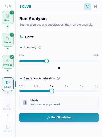
Core Count: Specifies the number of computation nodes to be used for the simulation. In general, increasing the number of nodes results in faster computation speed. Note that credits are consumed in proportion to the number of nodes used.
After clicking Run Simulation, the status will change to Running as shown in the figure.
7. Results
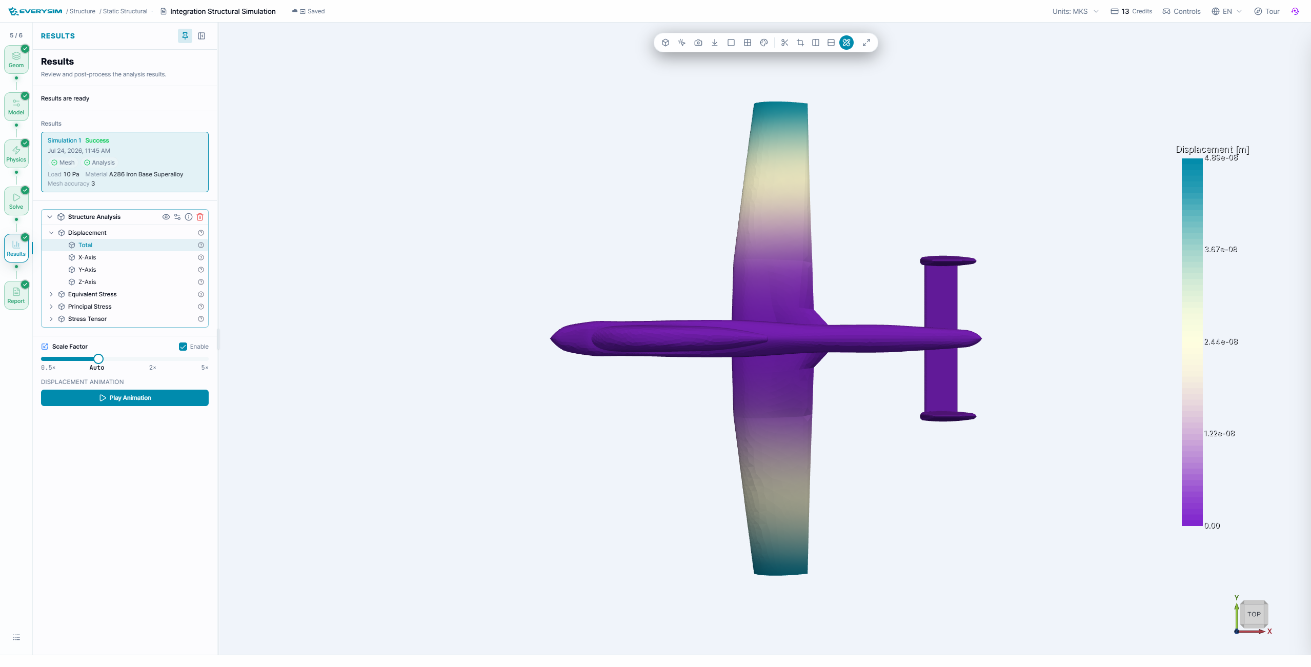
If the simulation completes successfully, a Results tree will appear, as shown in the figure, allowing you to review the results.
This screen provides three types of results:
-
Displacement: Shows the actual displacement.
-
Von Mises Stress: Assumes yielding occurs when the distortion energy (a component of strain energy) reaches a critical value. Commonly used to predict the onset of yielding by comparing with the yield stress.
-
Tresca Stress: Assumes yielding occurs due to the maximum shear stress. Generally provides more conservative results than Von Mises.
8. Report
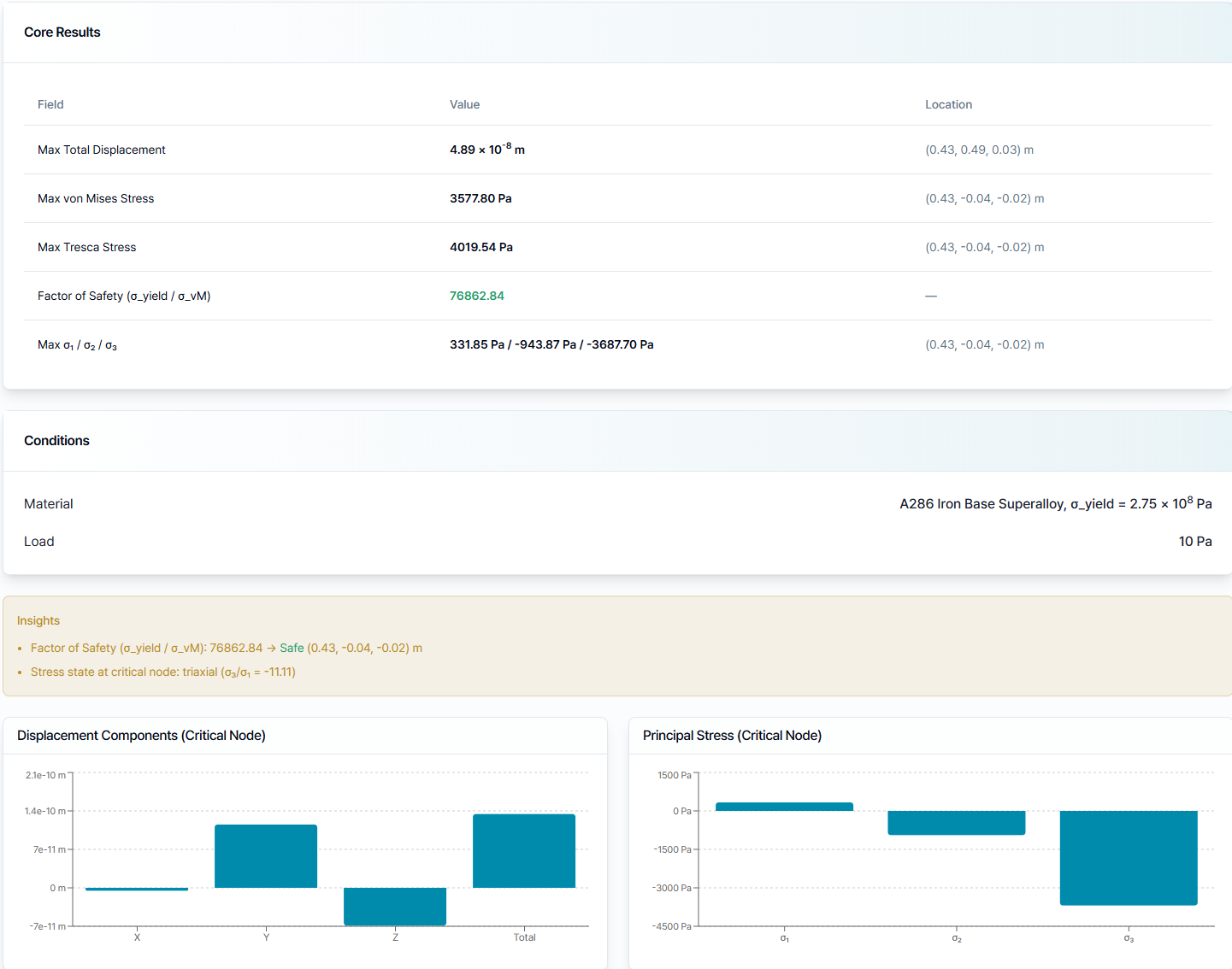
The report consolidates maximum displacement, von Mises stress, Tresca stress, factor of safety, principal stresses, critical locations, the assigned material, and the applied load. The insight panel and critical-node charts provide a compact numerical review alongside the 3D result.
Use these values only after confirming that the uploaded geometry, material assignment, constraints, loads, and mesh accurately represent the custom case being studied.
Need Assistance or Have Questions?
Frequently Asked Questions: FAQ Link
Support Inquiries: support@everysim.io