Vortex Propeller
This tutorial walks through a fast propeller analysis using the Vortex Method. Unlike a full CFD propeller analysis, this workflow represents the propeller with a parametric blade model and a vortex lattice, making it useful for quick lift, drag, blade loading, and wake checks before running more expensive simulations.
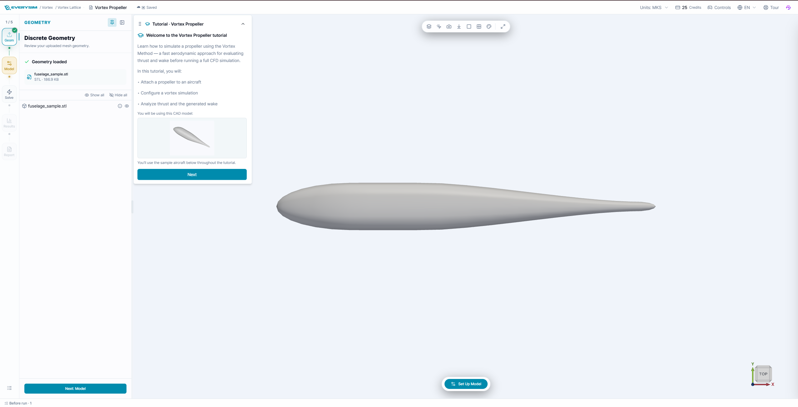
What You Will Learn
- Confirm the imported aircraft body in the Geometry stage.
- Create a parametric propeller from an airfoil profile.
- Position the propeller on the aircraft and set RPM.
- Configure the incoming flow and run the Vortex Method simulation.
- Inspect wake and blade-loading fields such as Cp and circ.
- Review the generated report for force and moment behavior.
The tutorial panel tracks each step with a checklist. Fields that need attention are highlighted automatically, and the Next button unlocks after the checklist for the current stage is complete.
1. Geometry
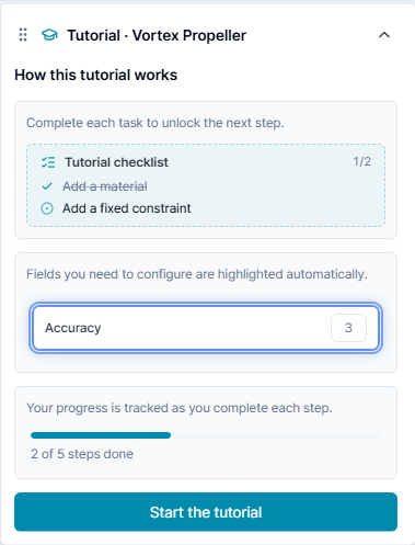
The tutorial starts with the aircraft body already loaded as fuselage_sample.stl. Use this stage to confirm the model is visible and ready before adding a propeller.
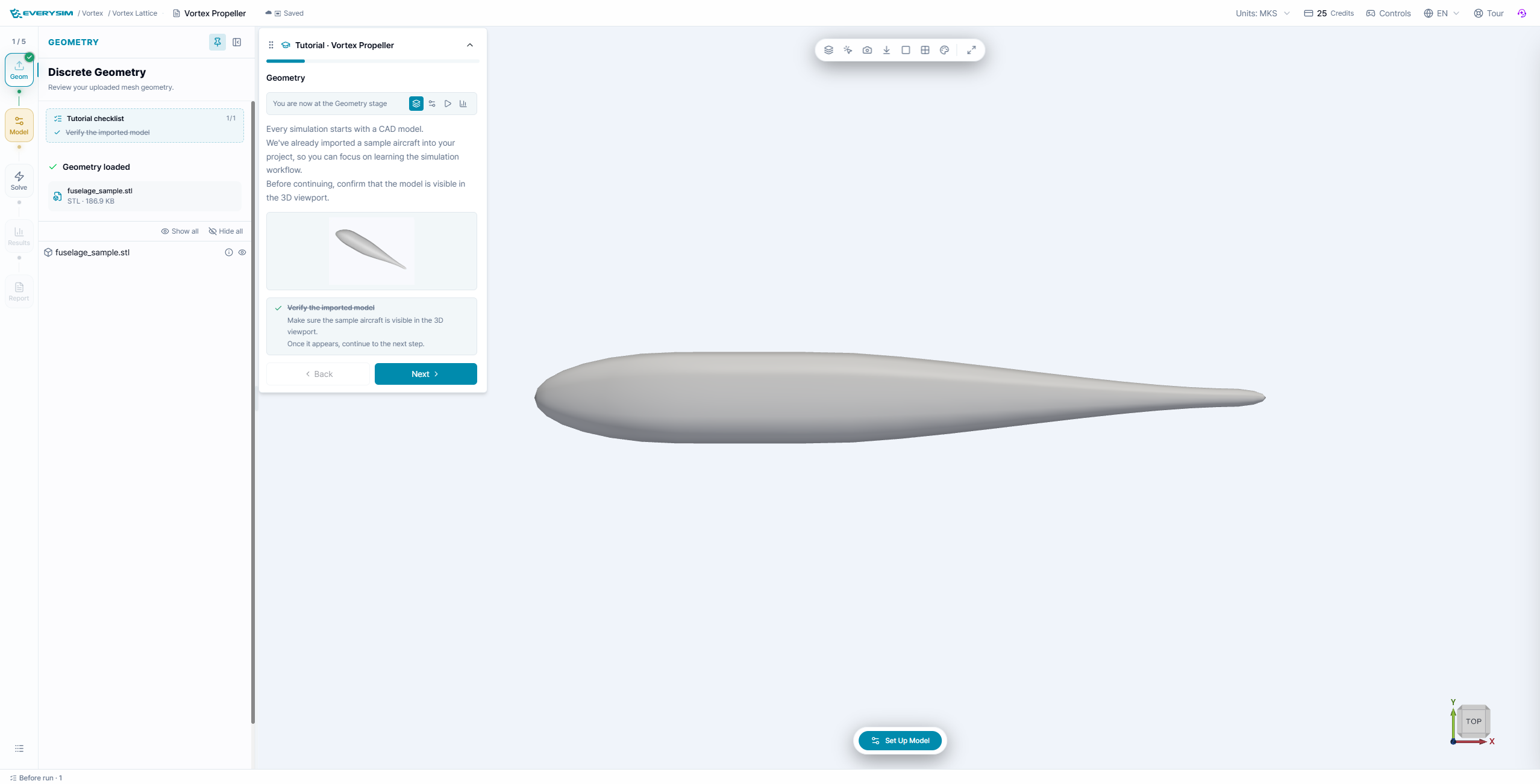
- Open the Geometry stage.
- Confirm that Geometry loaded is checked.
- Verify that
fuselage_sample.stlappears in the model tree. - Rotate or zoom the 3D viewport to confirm the aircraft body is visible.
The tutorial checklist marks this stage complete once the imported model has been verified.
2. Model
In the Model stage, create a propeller as a parametric model. The Vortex Method uses the airfoil and blade-section parameters to construct the blade lattice, so you do not need to import a detailed propeller CAD mesh.
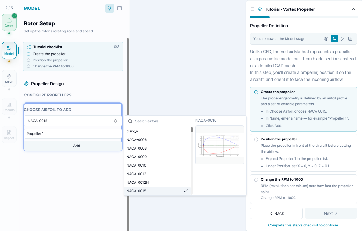
- In Choose Airfoil to Add, select NACA-0015.
- Enter a propeller name, such as
Propeller 1. - Click Add.
- Expand the new propeller item.
- Set the propeller position to X = 0, Y = 0, Z = 0.1.
- Set RPM to 1000.
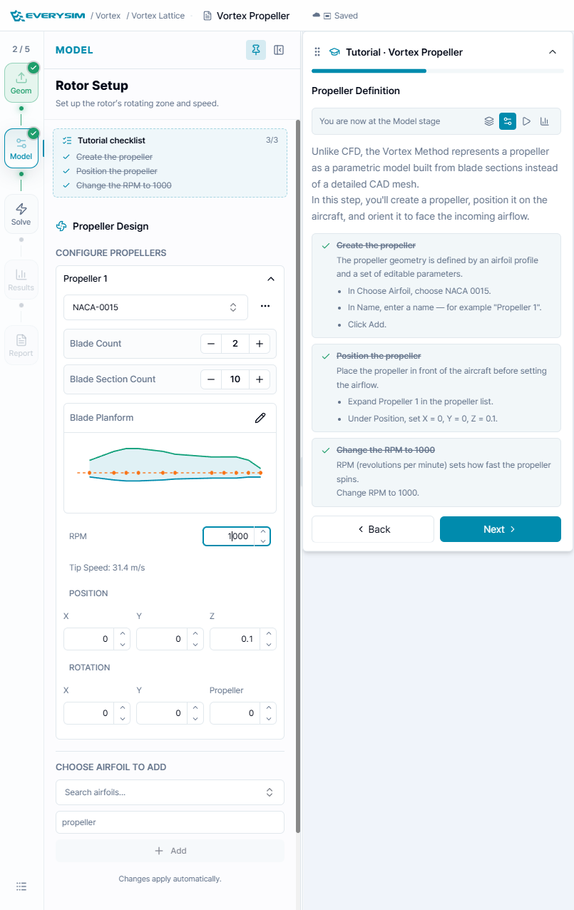
Use the blade preview to confirm that the planform looks reasonable. The example uses:
- Blade Count: 2
- Blade Section Count: 10
- Airfoil: NACA-0015
- RPM: 1000
- Position: X 0, Y 0, Z 0.1
The calculated tip speed is shown below the RPM field. If the tip speed becomes too high, reduce RPM or adjust the propeller geometry before solving.
3. Solve
The Solve stage sets the incoming flow and starts the analysis.
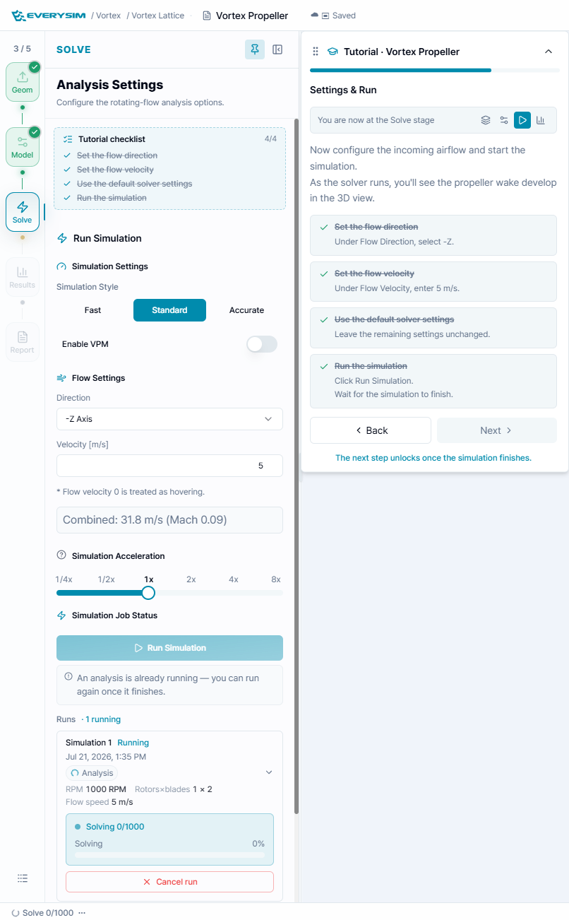
Use the tutorial checklist to apply the recommended settings:
- Set Simulation Style to Standard.
- Under Flow Settings, set Direction to -Z Axis.
- Set Velocity to 5 m/s.
- Leave the remaining solver settings unchanged.
- Click Run Simulation.
The run card displays the simulation state, RPM, rotor blade count, flow speed, and solving progress. Wait for the run to finish before moving to results.
4. Results
When results are ready, open the Results stage. The result tree includes body, rotor, lattice, and wake entries. The tutorial focuses on two fields:
- Cp: pressure coefficient over the blade or body.
- circ: circulation, which indicates bound vortex strength and where the blade is doing more work.
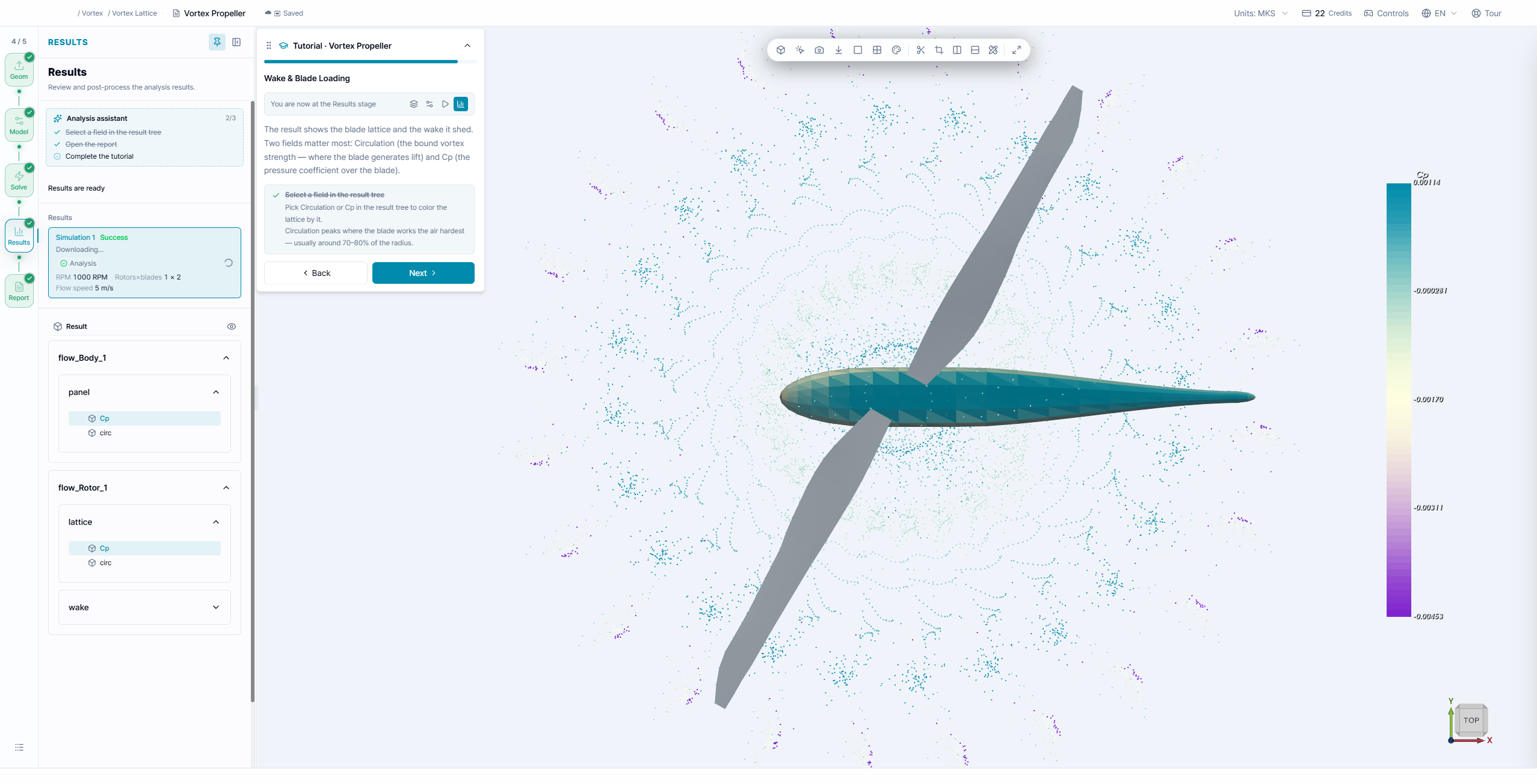
Recommended checks:
- Select a field in the result tree, such as Cp under the lattice or body result.
- Inspect the colored blade or body surface.
- Review the wake points around and behind the propeller.
- Use camera controls, color map, and visibility toggles to isolate the structures you need.
For a healthy quick check, look for a coherent wake pattern and plausible loading concentration across the blade span. Strong peaks often appear around the productive mid-to-outboard region of the blade.
5. Report
The Report stage summarizes the run with performance plots and force/moment distributions.
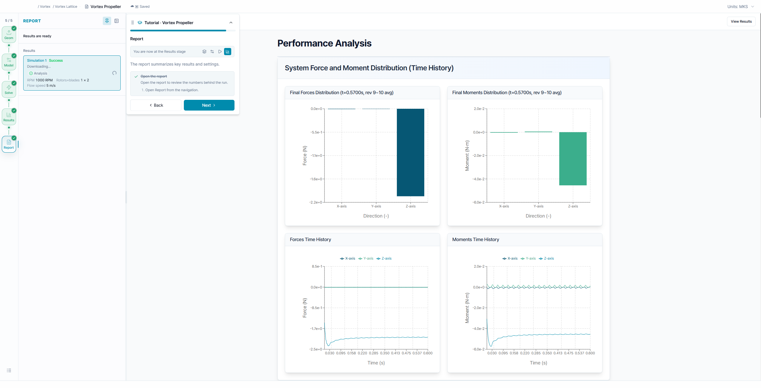
Use the report to review:
- Final force distribution by axis.
- Final moment distribution by axis.
- Time history of forces and moments.
- Whether forces converge toward a stable value after the initial transient.
The force and moment plots help confirm whether the propeller produces the expected thrust direction and whether moment behavior is reasonable for the selected propeller placement.
Practical Notes
- Use Vortex Propeller when you need fast aerodynamic feedback before committing to a full CFD run.
- Use the same setup to compare RPM, airfoil, blade count, blade section count, and propeller position.
- If the propeller seems to create unrealistic loads, check orientation, RPM, airfoil selection, and whether the propeller is facing the incoming airflow.
- If you need detailed viscous flow, wall effects, or rotating-domain CFD, continue with one of the CFD propeller tutorials.