FEA: Static Structural
This tutorial performs a steady structural analysis of the supplied bracket-like drone component. You will assign a material, define a fixed support and pressure load, solve the model, inspect deformation and stress fields, change the color map, and read the structural report.
What you will learn
- Confirm the sample geometry and orientation.
- Assign material properties before applying loads.
- Distinguish a fixed support from an applied pressure.
- Run a mesh-based static solution and check its status.
- Read total displacement, equivalent stress, principal stress, and safety factor.
1. Geometry
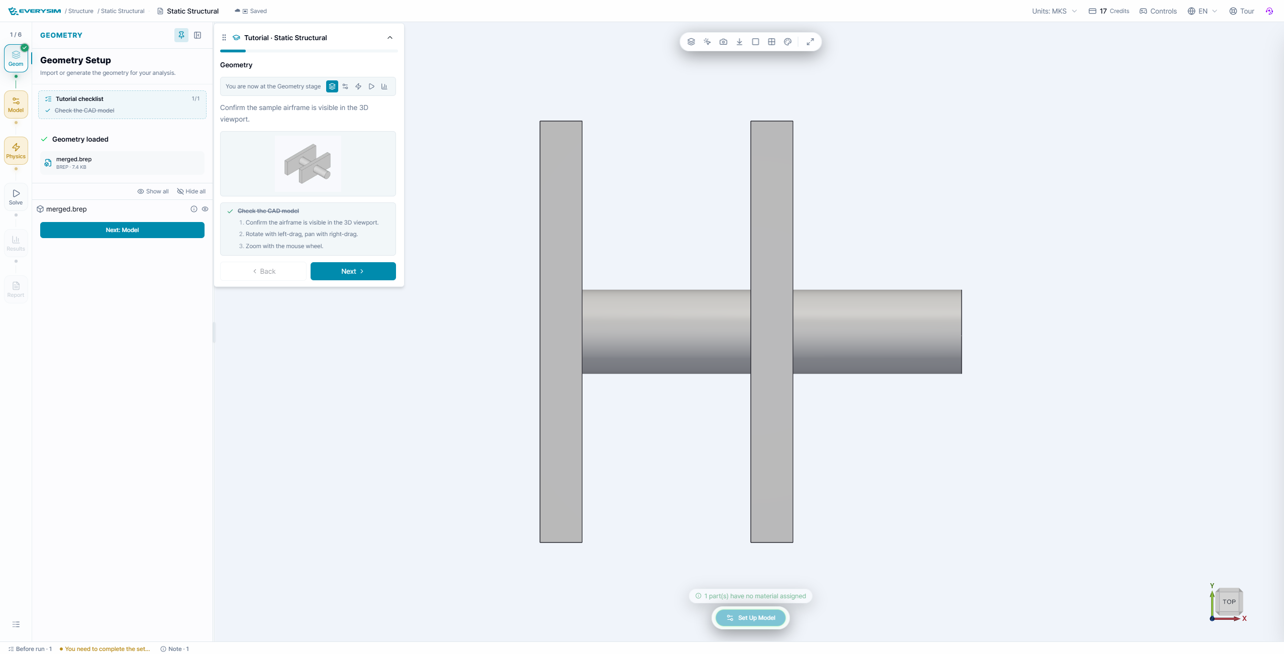
Confirm that the prepared component is visible and that the model tree contains the two plates and the connecting cylinder. The geometry is intentionally simple so the load path is easy to follow. Orbit the model and identify the face that will be fixed before advancing.
2. Model: assign material
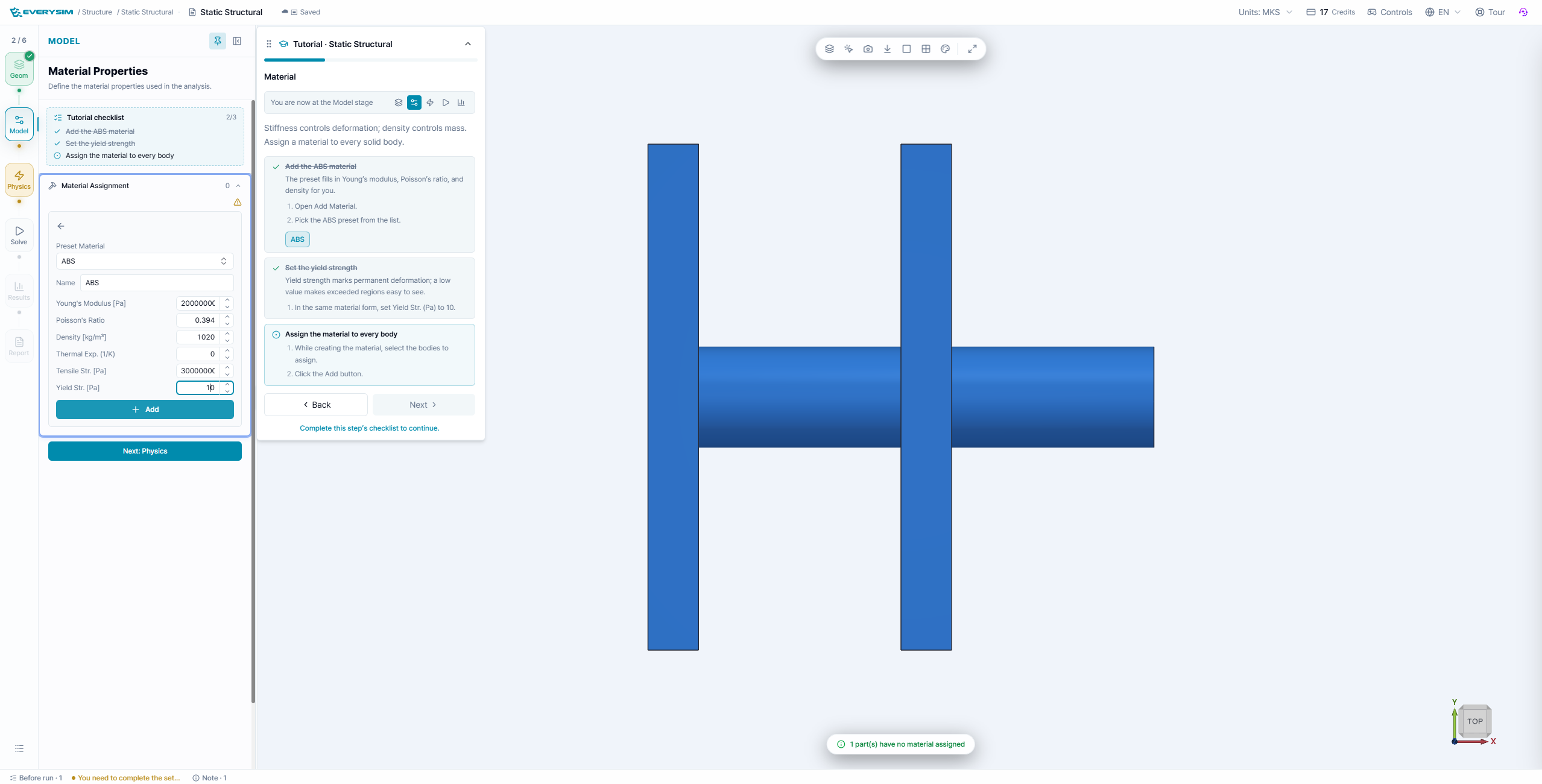
Assign the tutorial material to every body. The material card supplies the elastic modulus, Poisson ratio, density, and yield strength used by the solver. Check that no body remains unassigned; a material mismatch makes stress comparisons meaningless.
3. Physics: constraints and load
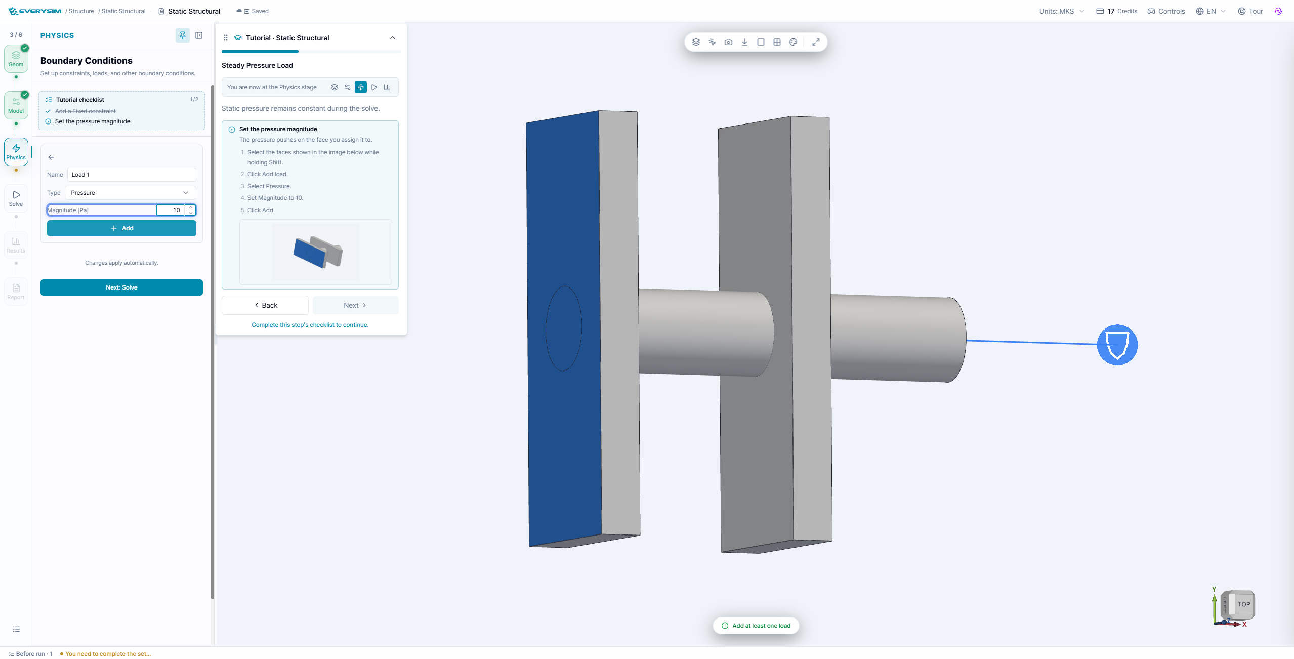
- Add a Fixed constraint to the support face highlighted by the tutorial.
- Add the tutorial Pressure load to the indicated face.
- Confirm the load arrow points into the part in the intended direction.
- Check that the fixed face and loaded face are not accidentally the same face.
The fixed support removes rigid-body motion. The pressure creates the steady response. If the model is under-constrained, the solve may fail or the displacement may become unbounded.
4. Solve and monitor the run
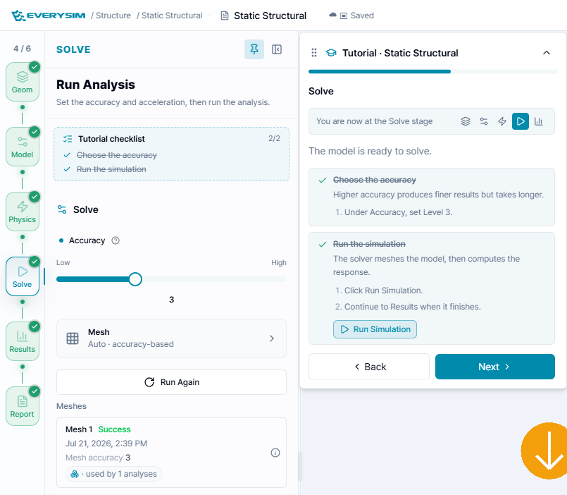
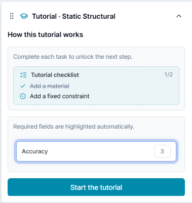
Set Accuracy to the tutorial level 3, leave the mesh on the automatic accuracy-based option, and click Run Simulation. The workbench generates the mesh and reports the run state in the analysis card.
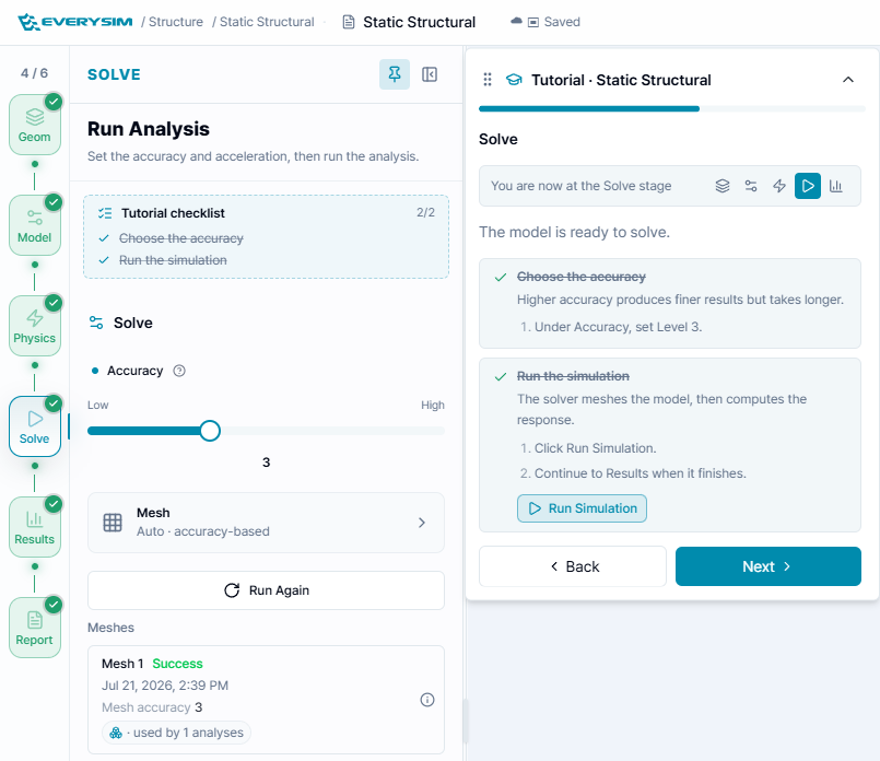
Wait until both Mesh and Analysis show success. Do not interpret a partially solved contour as a final result.
5. Results: displacement and stress
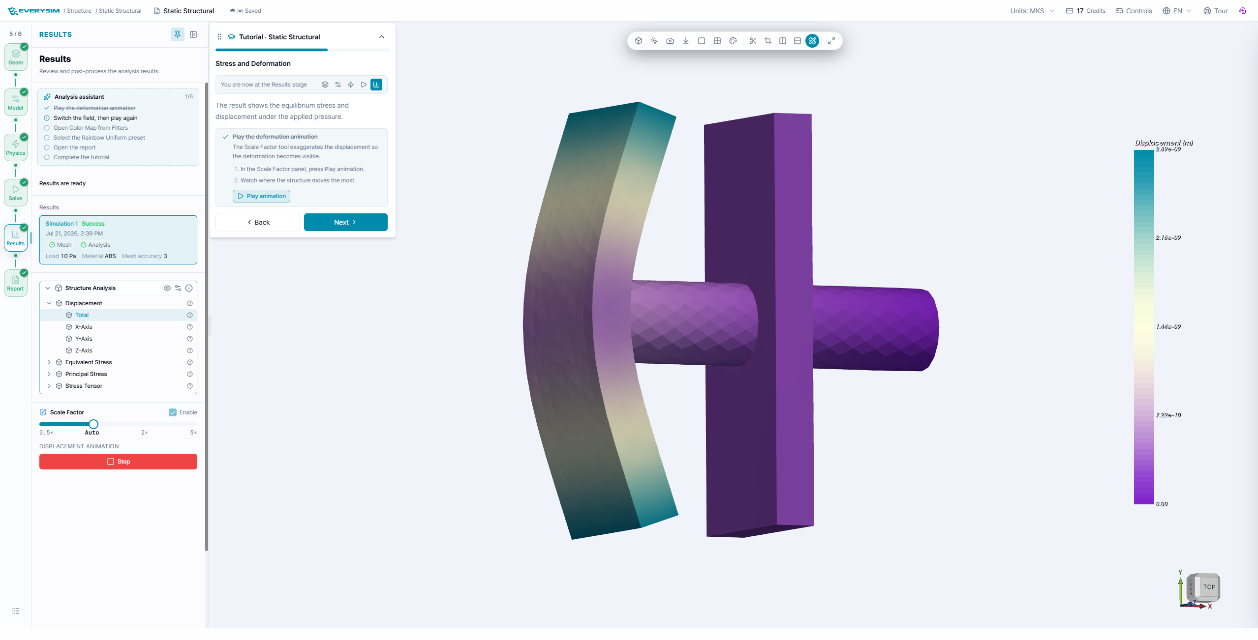
Start with Total Displacement. The undeformed shape remains visible while the color map shows the relative response. The displayed deformation can be scaled for readability, so use the legend and report for numerical values.
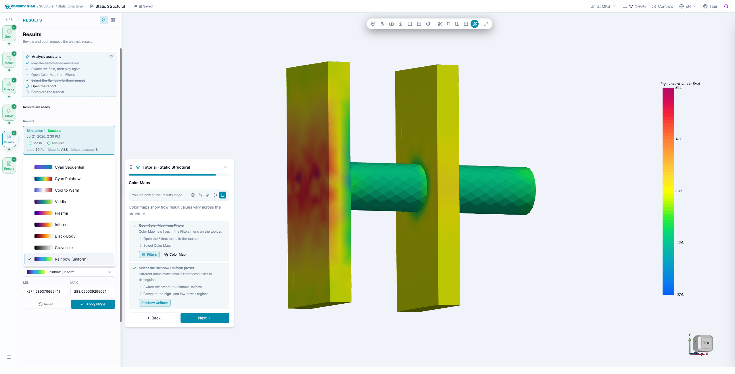
Open the result tree to compare Equivalent Stress, von Mises, Tresca, and Principal Stress. Use Filters → Color Map to choose a consistent palette. A hot spot at a sharp edge may be mesh-sensitive; refine the mesh or inspect a nearby averaged region before making a design decision.
6. Report and interpretation
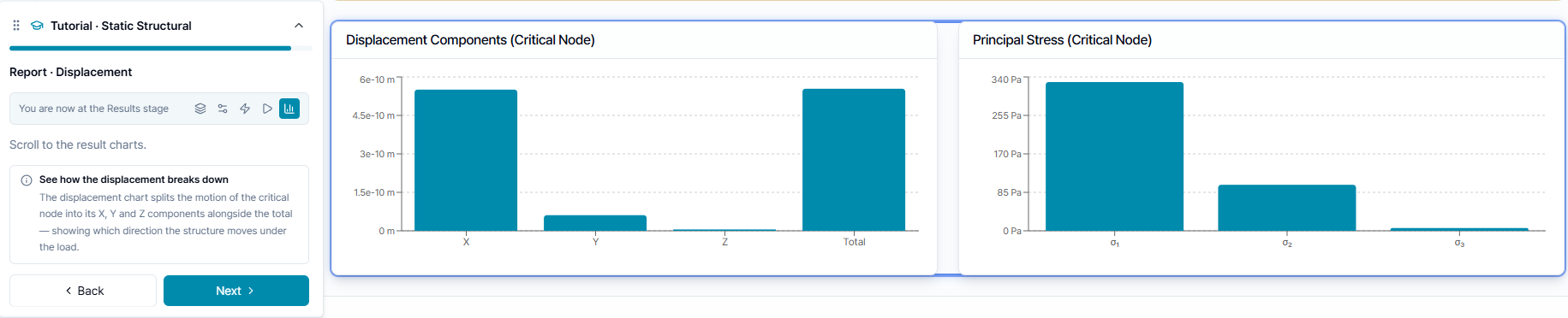
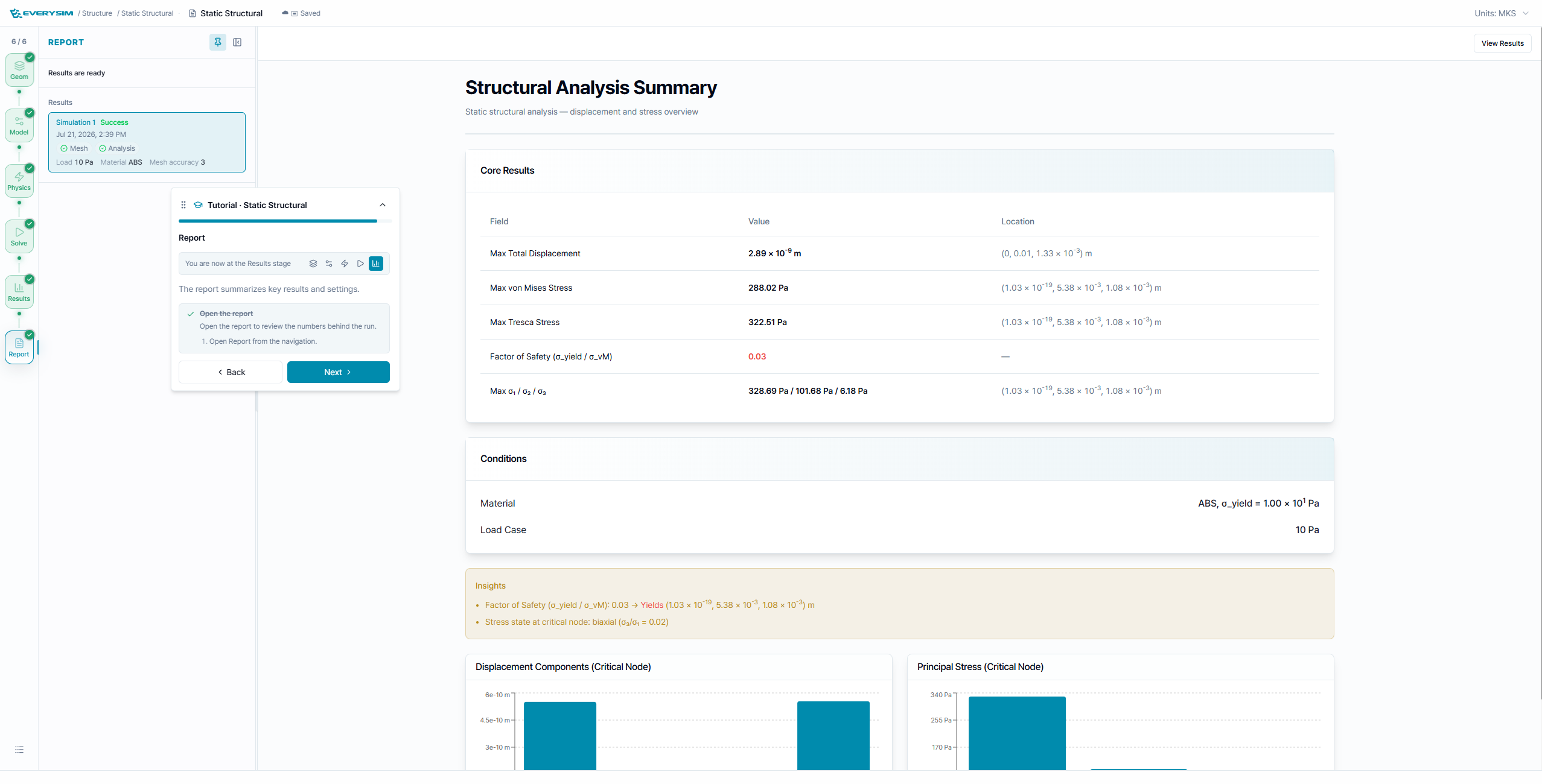
The report gathers the maximum displacement, maximum equivalent and Tresca stresses, critical location, and factor of safety. Use the factor of safety as a screening value:
If the factor of safety is below the design target, review the material, support, load magnitude, mesh, and unit system before redesigning the part. A static result is meaningful only when those inputs represent the physical installation.
Completion checklist
- Every body has the intended material.
- The support removes rigid-body motion without over-constraining the part.
- The pressure magnitude, direction, and selected face are correct.
- Mesh and analysis both finish successfully.
- Displacement, stress, color map, and report values have been reviewed together.