CFD: Rotating Machinery
This tutorial runs a steady CFD analysis of a propeller inside a rotating-frame (MRF) fluid domain. You will confirm the sample geometry, size the rotating zone, define freestream and RPM conditions, solve the flow, inspect the propeller surface and wake, and read the performance report.
What you will learn
- Confirm the prepared
propeller_sample.stepgeometry. - Create an inner rotating fluid zone and keep the surrounding flow domain stationary.
- Set wind speed, angle of attack, rotation axis, direction, and RPM.
- Run the mesh and solver with the tutorial accuracy settings.
- Compare fields on the complete flow volume, the propeller body, and a saved cut.
- Use streamlines and the report to connect the flow pattern to thrust, torque, and convergence.
The tutorial panel is part of the workbench. It highlights the required field, records completed checks, and unlocks Next only when the current stage is valid.
1. Geometry: confirm the propeller
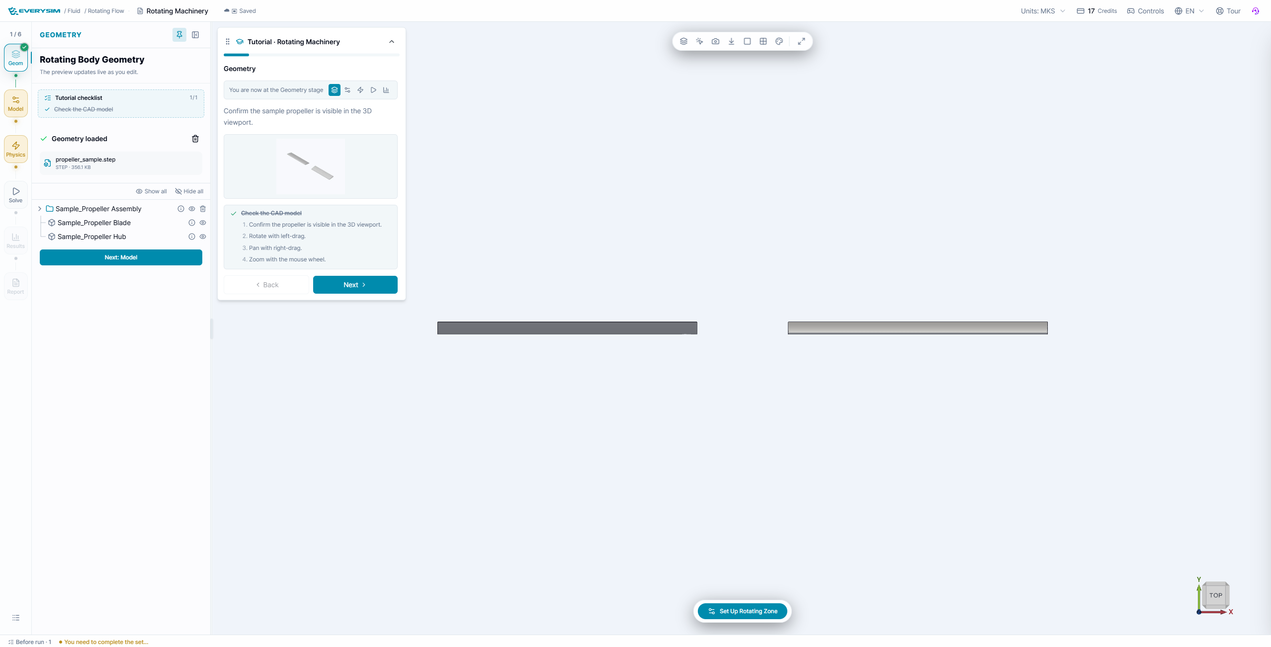
The prepared model contains a propeller assembly with a blade and hub. In the Geometry stage:
- Confirm that
propeller_sample.stepis loaded. - Check that
Sample_Propeller Assembly,Sample_Propeller Blade, andSample_Propeller Hubappear in the model tree. - Orbit the viewport to make sure the blade is visible and the axis is not accidentally reversed.
- Select Next: Model.
This is a readiness check. Do not change the CAD scale or repair the model inside this tutorial.
2. Model: create the rotating zone
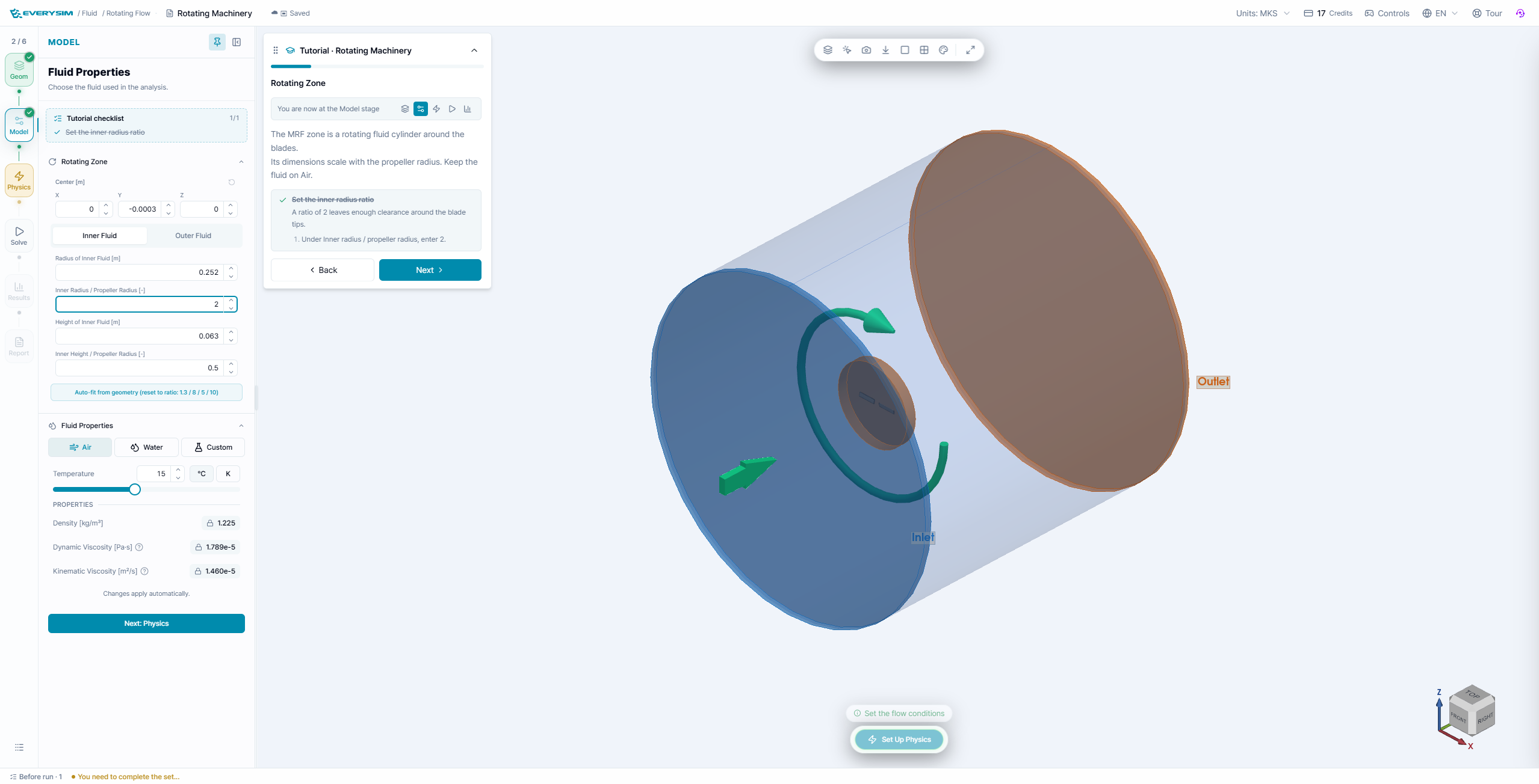
The solver uses a cylindrical multiple-reference-frame (MRF) region around the blades. The inner region rotates relative to the outer flow volume.
Use the tutorial values shown in the workbench:
- Center: keep the sample center at
X = 0,Y = -0.0003,Z = 0m. - Inner radius / propeller radius:
2. - Inner height / propeller radius:
0.5. - Inner fluid: Air.
- Keep the inlet and outlet faces on the correct sides of the cylinder.
The blue cylinder is the rotating zone and the green curved arrow shows its direction. If the cylinder is too small, blade tips can intersect the interface; if it is too large, the run becomes unnecessarily expensive. Use Auto-fit from geometry when the preview does not surround the blade with clearance.
3. Physics: define flow and rotation
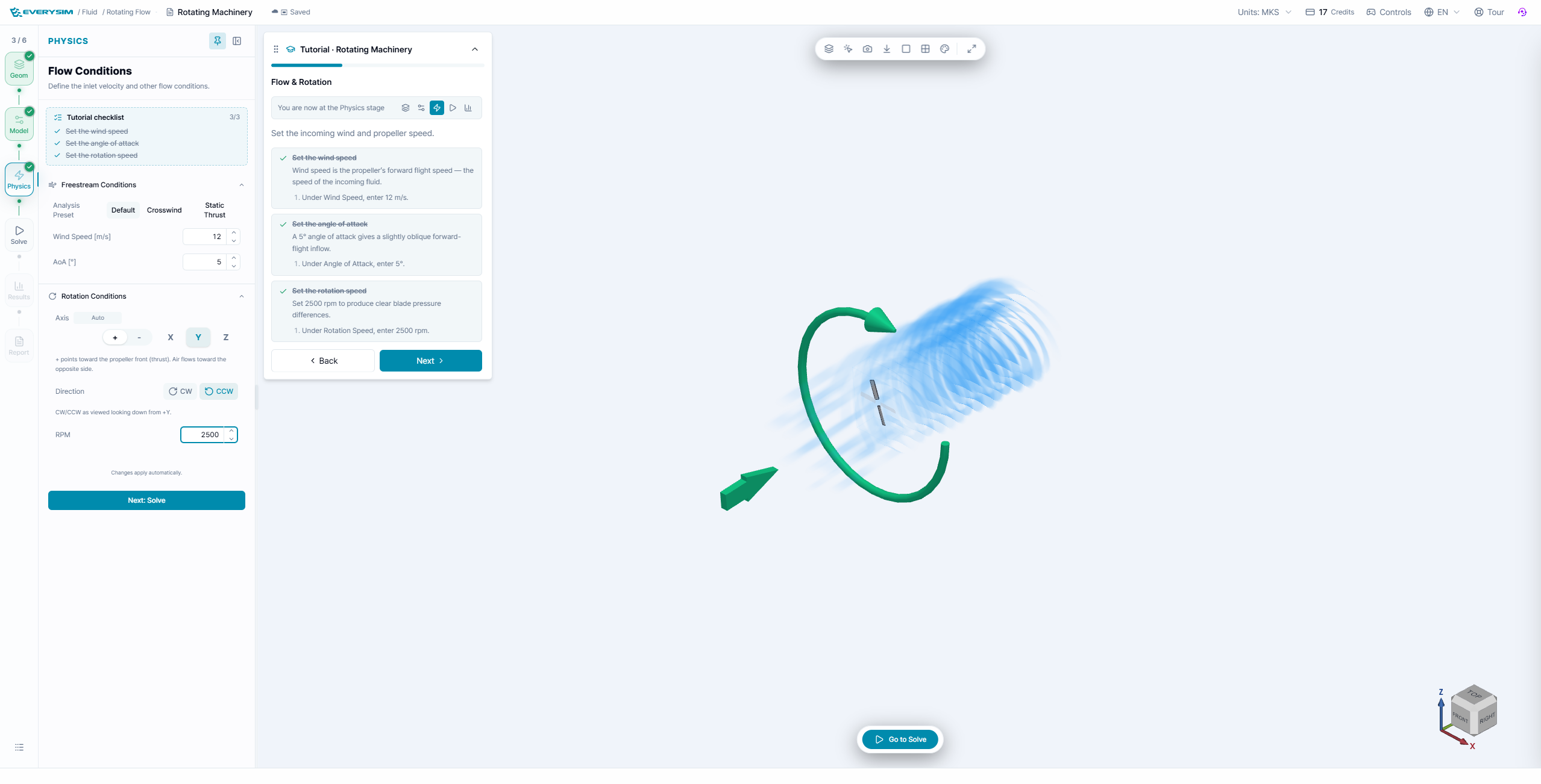
In Physics, set the freestream and rotation conditions:
- Wind speed:
12 m/s. - Angle of attack:
5°. - Rotation axis:
Y. - Direction: CCW as viewed looking down the positive axis.
- RPM:
2500.
The blue flow streaks indicate the incoming velocity and the green ring indicates the rotor direction. Check both before solving: reversing the axis or direction changes the sign of torque and can make the wake look physically inverted.
4. Solve and check convergence
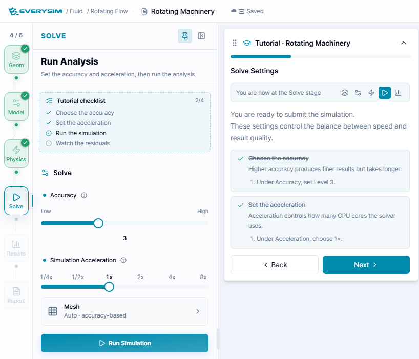
- Set Accuracy to
3. - Set Simulation Acceleration to
1x. - Leave Mesh at Auto – accuracy-based.
- Click Run Simulation.
The solver first creates the mesh and then computes the rotating-frame flow. The run card records the RPM, wind speed, angle of attack, and mesh accuracy so you can compare later runs.
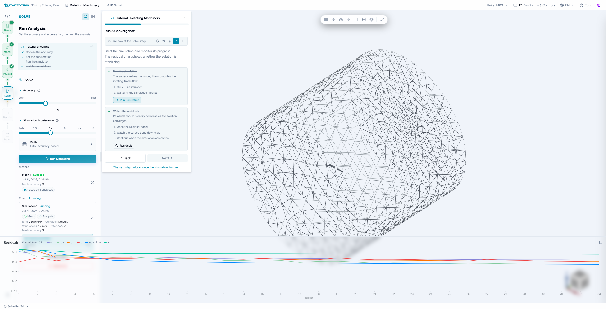
Open Residuals while the run is active. Curves should generally decrease and flatten. A flat residual curve is useful evidence of stabilization, but always combine it with the final field plots and force history.
5. Results: inspect the propeller and fields
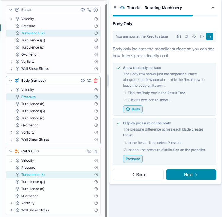
The result tree contains the complete flow volume, the propeller surface, and saved sections. Start with Pressure on Body (surface) to see the pressure difference that produces thrust. Then compare Velocity, Turbulence, Vorticity, and Wall Shear Stress on the full result.
When comparing fields:
- Select the field under the object you want to study.
- Use the eye controls to hide the volume or body temporarily.
- Read the color legend rather than judging color alone.
- Keep the same camera and field range when comparing two runs.
6. Cut sections and streamlines
Use Cut to expose values through the rotating flow rather than only on the blade surface. A mid-plane cut is especially useful for locating the accelerated wake and swirl.
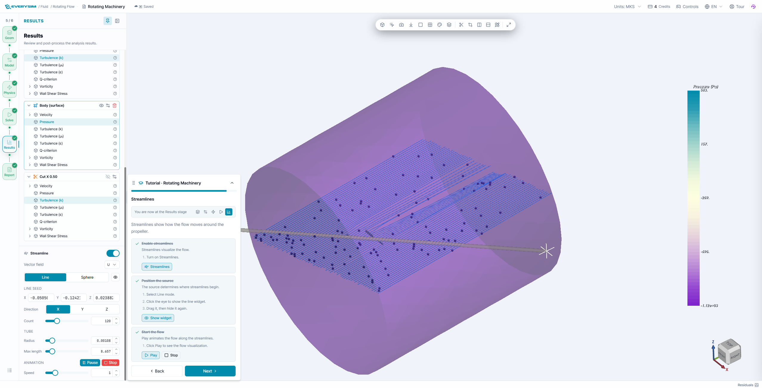
To create a useful streamline view:
- Turn on Streamline.
- Choose the velocity vector field.
- Use a line seed upstream of the rotor or a sphere seed around the hub.
- Adjust count, radius, and maximum length so the wake remains readable.
- Press Play to animate the flow.
The wake should move downstream while also showing the rotation induced by the blade loading. If the wake travels upstream, revisit the flow direction and rotation sign.
7. Report: performance and convergence
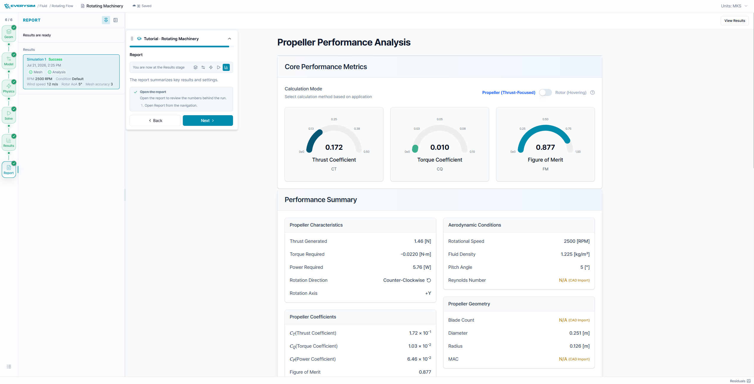
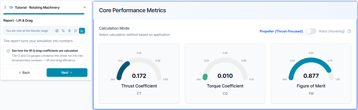
The report summarizes the run using thrust, torque, power, and figure-of-merit metrics. The example run reports approximately CT = 0.172, CQ = 0.010, and FM = 0.877; values change when the geometry, RPM, wind speed, or mesh changes.
Interpret the values together:
- Thrust coefficient (CT) compares thrust after nondimensionalizing by density, RPM, and propeller size.
- Torque coefficient (CQ) represents the torque required to keep the propeller turning.
- Figure of merit (FM) is an efficiency indicator for the thrust-focused calculation.
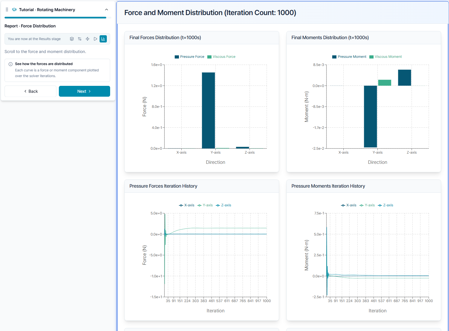
The force and moment charts separate pressure and viscous contributions by axis and show their iteration histories. Use the histories to verify that the final values have stopped changing materially before comparing designs.
Practical checks
- Confirm the rotation axis and direction before every new run.
- Keep the rotating zone clear of the blade tips and hub.
- Use the same reference size and operating condition when comparing CT, CQ, or FM.
- Treat the screenshot values as an example result, not a guaranteed benchmark for another CAD model.