CFD: Static Wind Propeller
This tutorial evaluates a propeller in still air. The Static Thrust preset sets the incoming wind speed to zero while the rotor continues to spin, making the run useful for comparing static thrust, torque, wake development, and propeller efficiency.
What you will learn
- Load and verify the prepared propeller model.
- Set the air properties and rotating-zone size.
- Switch to the Static Thrust preset and define rotor angle of attack.
- Run the CFD analysis with the tutorial mesh and accuracy settings.
- Inspect a saved wake section and turbulence on the cut.
- Read thrust, torque, power, figure of merit, and force/moment histories.
1. Geometry: verify the sample
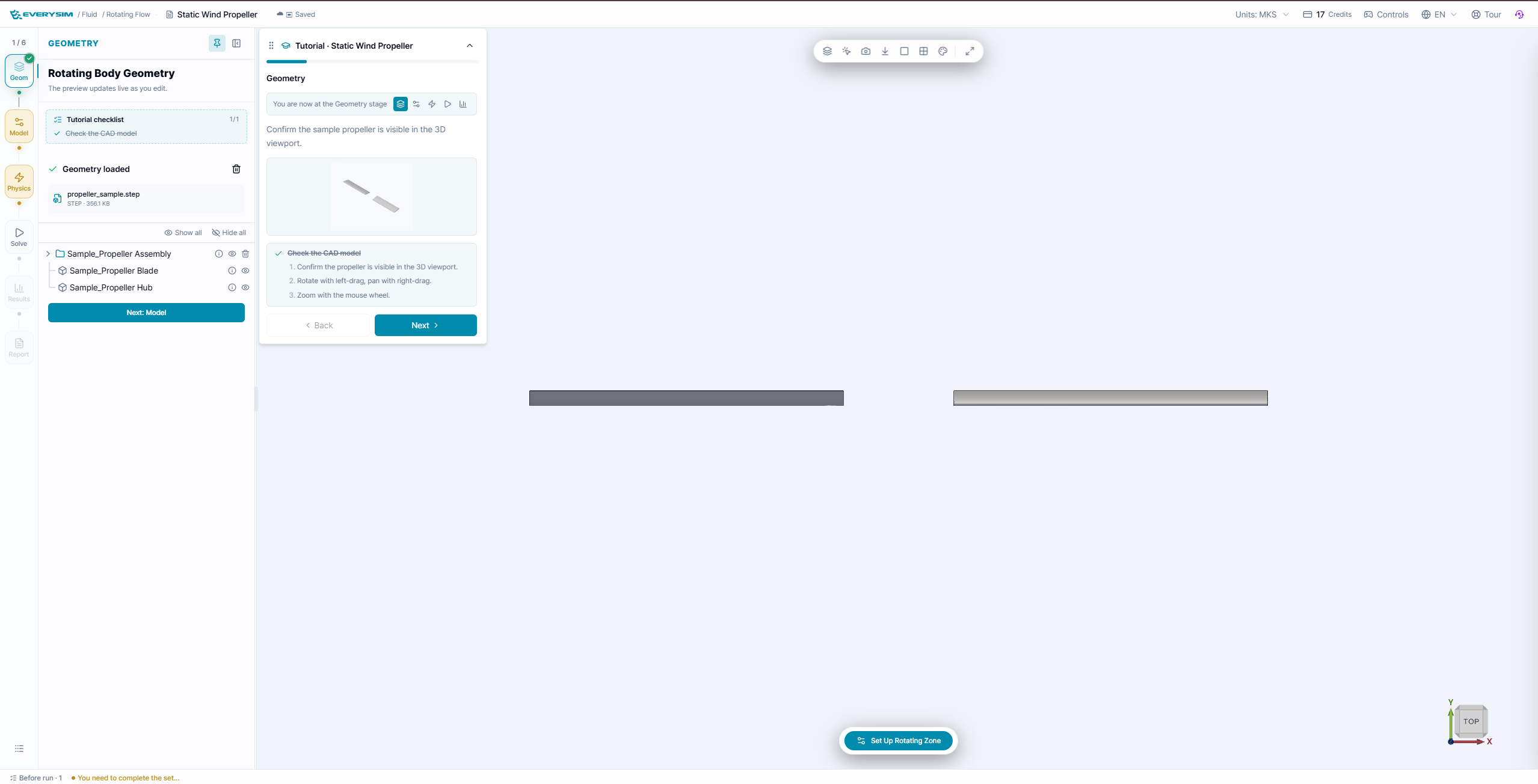
Confirm that the prepared propeller_sample.step file is loaded, the propeller is visible in the viewport, and the model tree contains the expected blade and hub parts. Rotate the view once to confirm the propeller axis before moving to Model.
2. Model: air and rotating zone
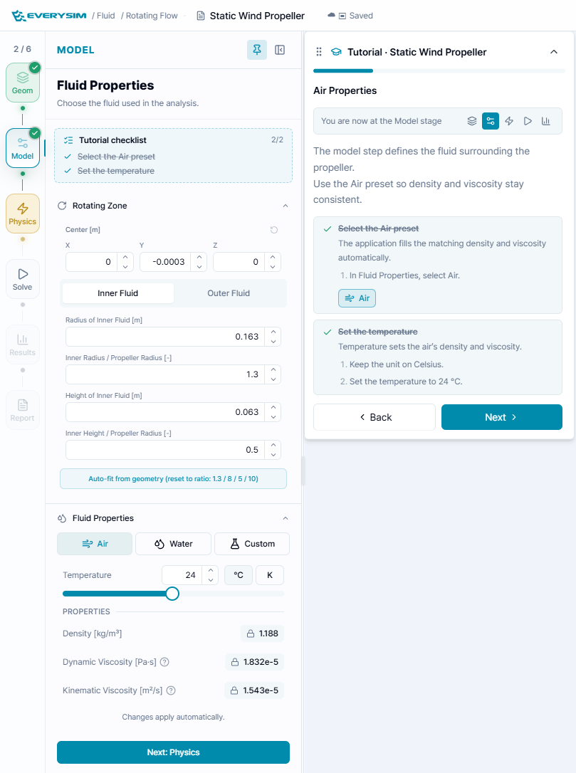
Select Air and keep the tutorial temperature at 24 °C. The application fills density and viscosity from the preset so the static-thrust result remains reproducible.
For the rotating zone, use the tutorial values:
- Inner radius / propeller radius:
1.3. - Inner height / propeller radius:
0.5. - Keep the sample center and the automatically fitted geometry.
The zone must cover the blades with clearance. If the tip intersects the interface, use Auto-fit from geometry and confirm the preview before continuing.
3. Physics: static-thrust conditions
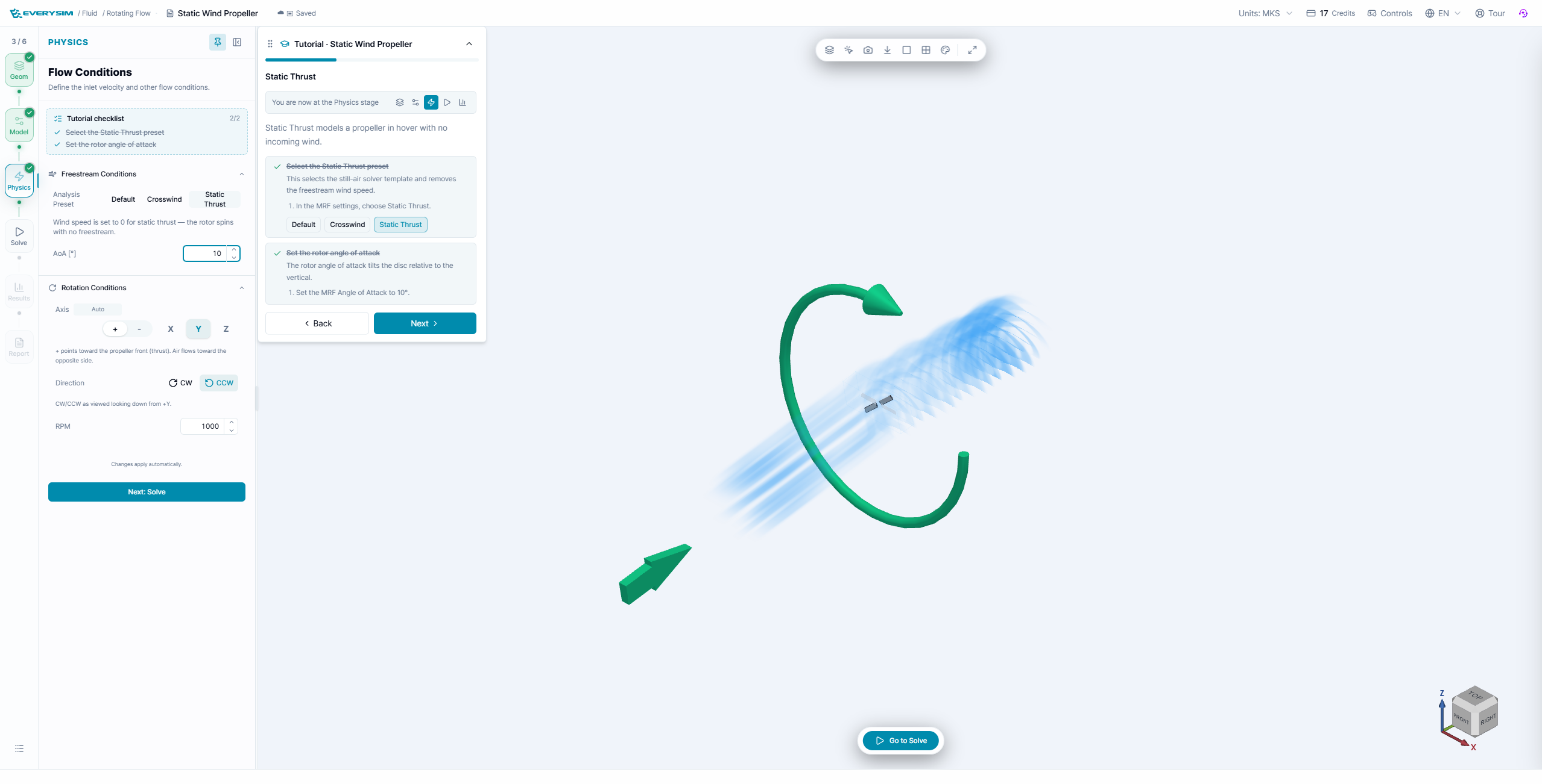
Under Freestream Conditions:
- Choose Static Thrust. The wind speed becomes
0 m/s. - Set the rotor angle of attack to
10°. - Keep the rotation axis on
Yand the tutorial direction CCW. - Use
1000 RPMfor the tutorial run.
Static thrust is a hovering-like condition: the rotor produces a wake without a forward freestream. Do not add a nonzero wind speed unless you intentionally want a different operating point.
4. Solve
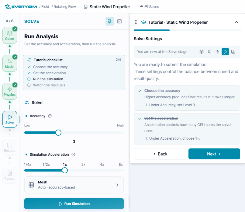
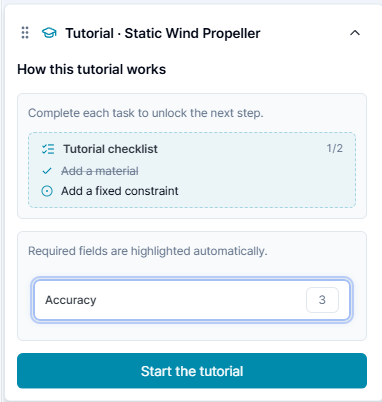
Set Accuracy to 3, Simulation Acceleration to 1x, and keep the mesh on Auto – accuracy-based. Click Run Simulation and wait for the mesh and analysis to complete.
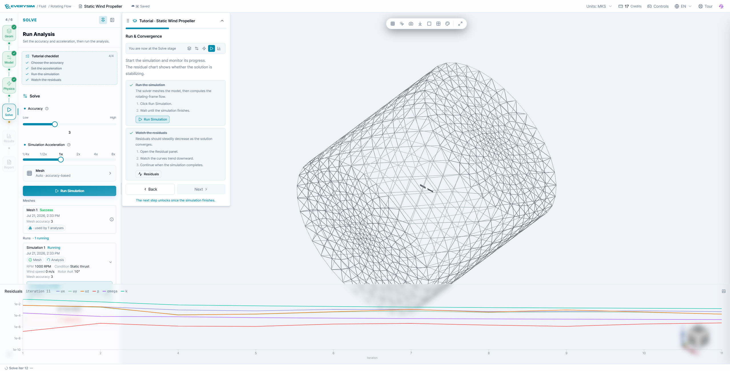
Use the residual panel to check that the solution is settling. For static thrust, also watch whether the force history reaches a stable value; the final report is the deciding check.
5. Results: inspect a wake section
Create an X cut at the tutorial position and click Save section. The saved section appears as its own result-tree entry with the same fields as the original flow volume.
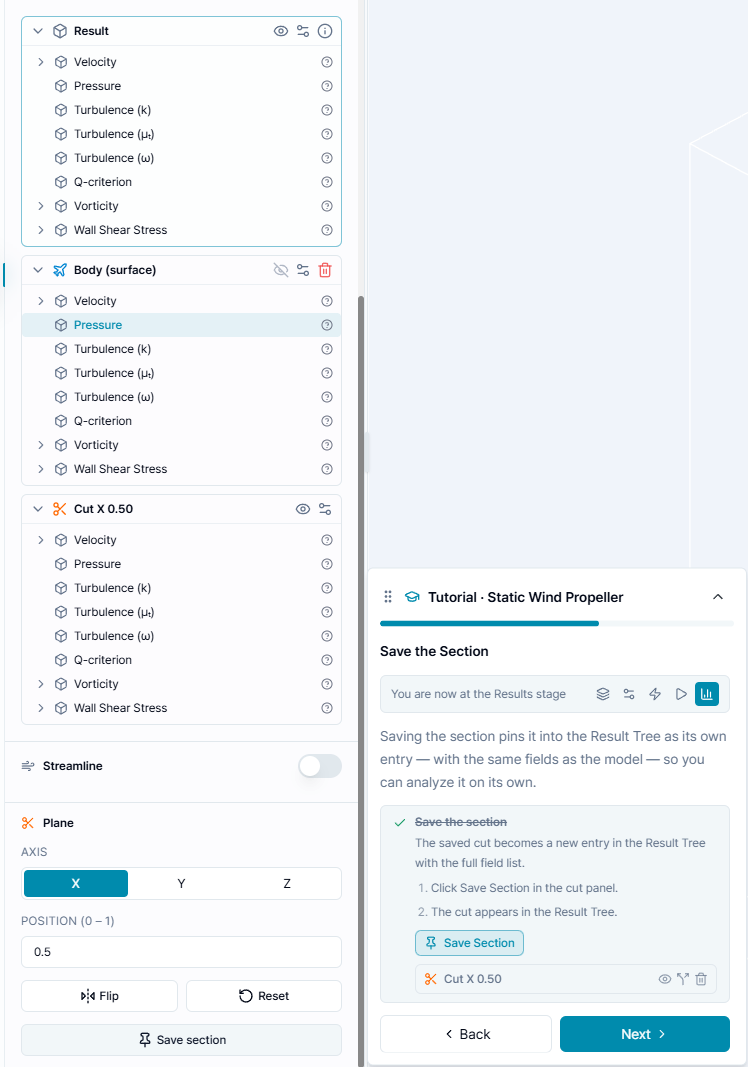
To isolate the wake:
- Hide the main result body with its eye control.
- Leave the saved cut visible.
- Select Pressure or Velocity on the cut.
- Set the camera to the cut axis when you need a head-on view.
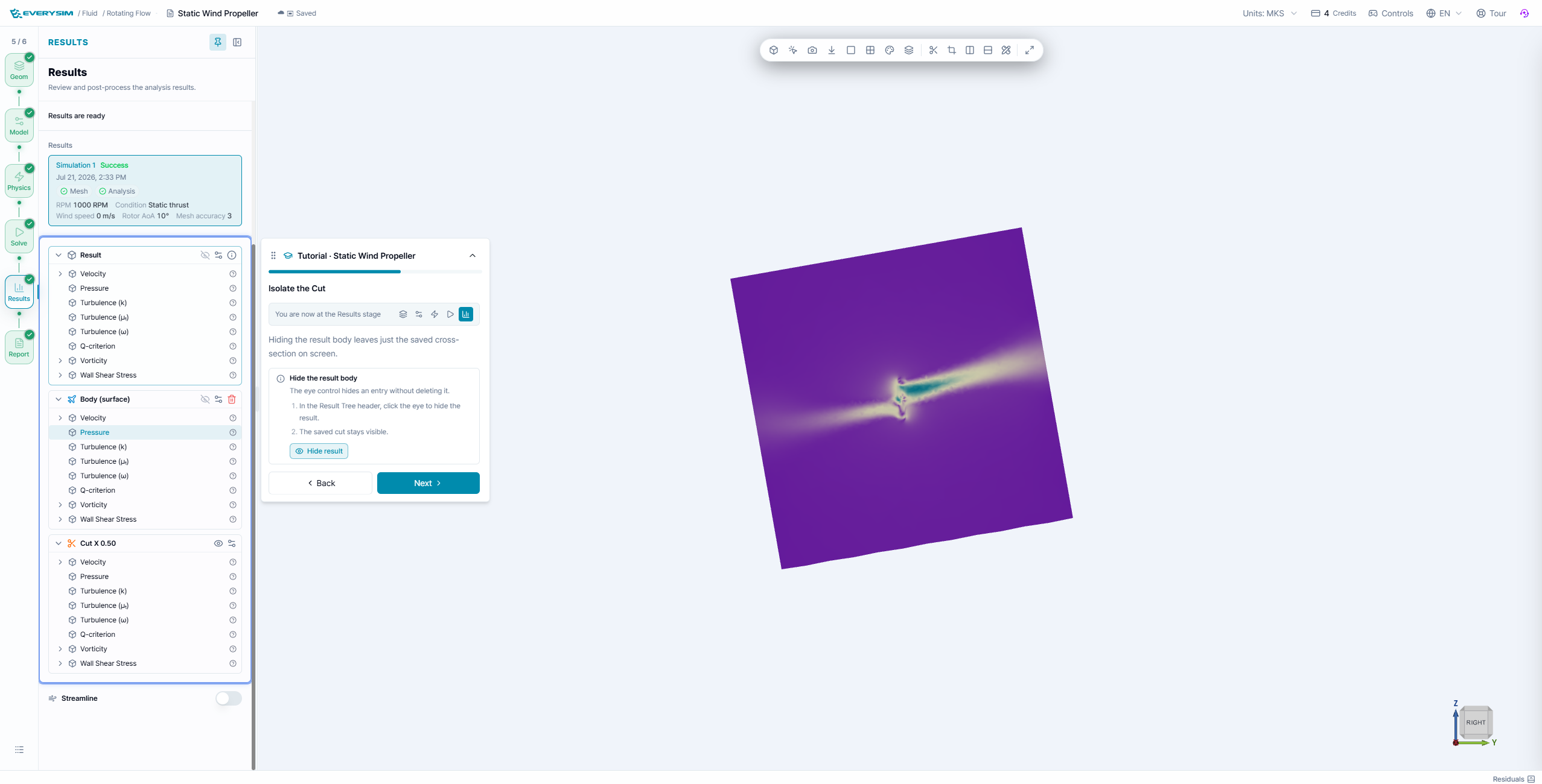
The cut makes the accelerated jet and pressure disturbance behind the rotor easier to distinguish from the surrounding still air.
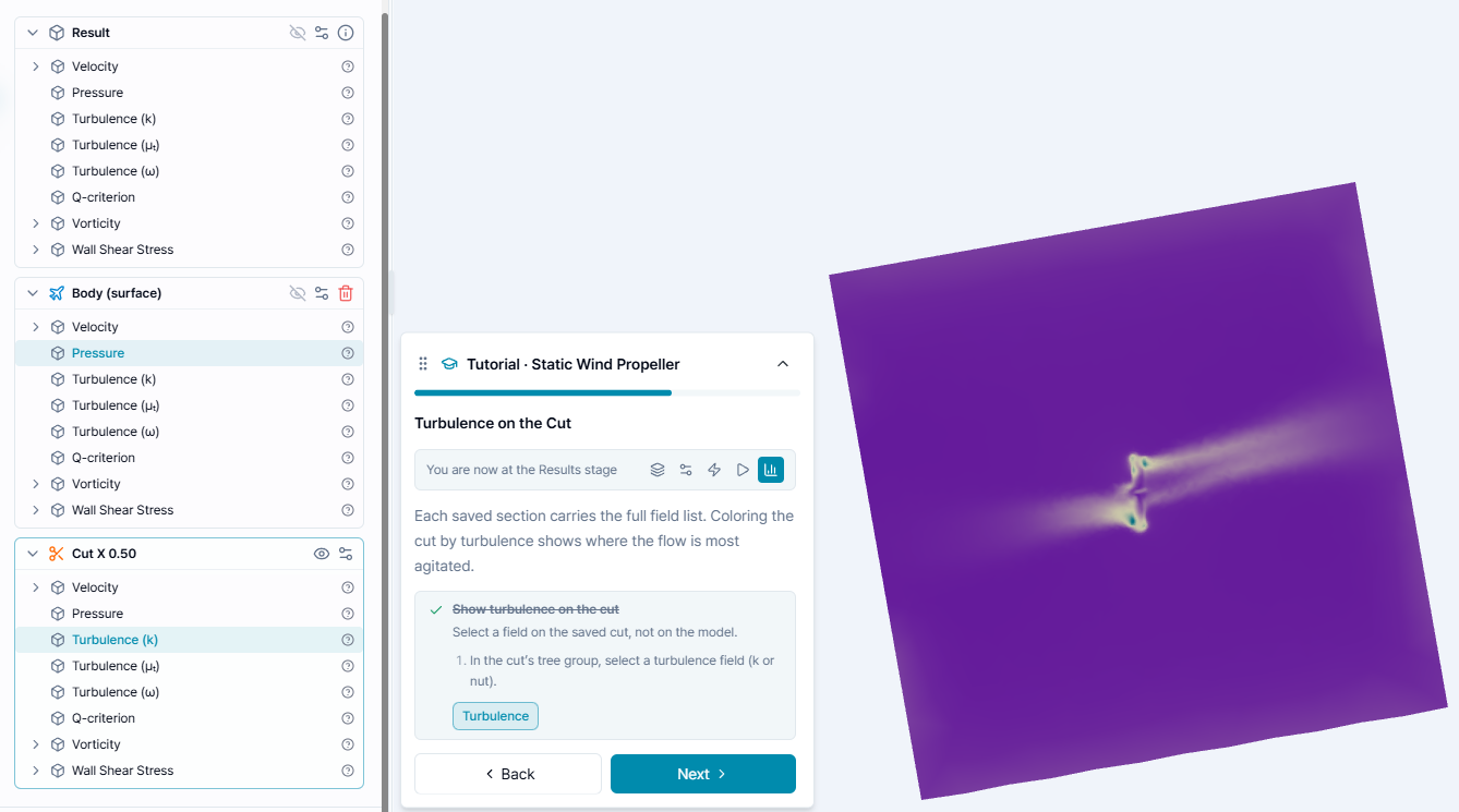
Select a turbulence field on the saved cut, not on the original body. Concentrated values near the blade plane and wake indicate where the rotor has disturbed the flow.
6. Report: static performance
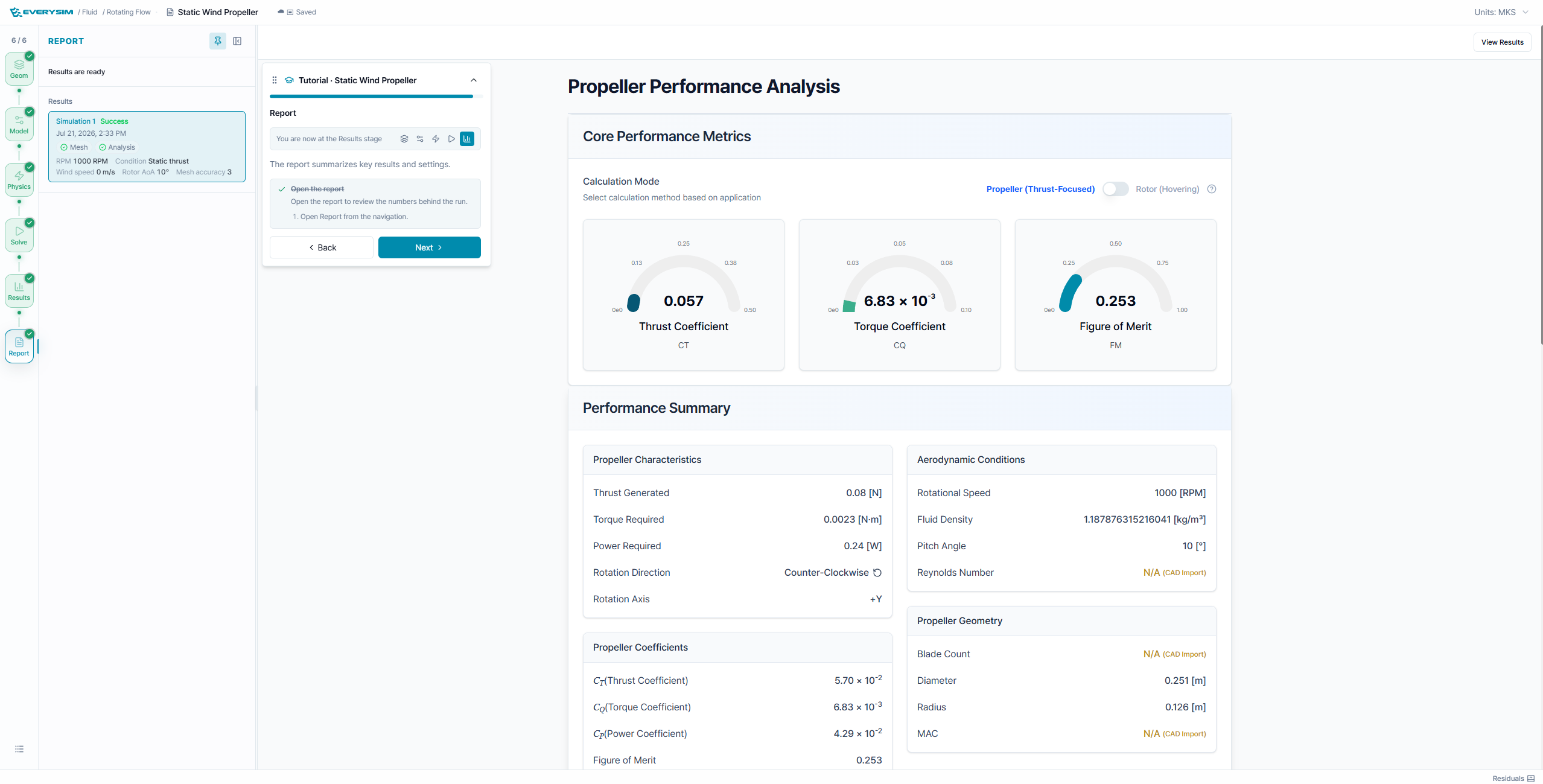
The example report shows approximately CT = 0.057, CQ = 6.83 × 10⁻³, and FM = 0.253, with about 0.08 N thrust at 1000 RPM. These numbers are tied to the supplied geometry and settings; use them as a reading guide rather than a universal target.
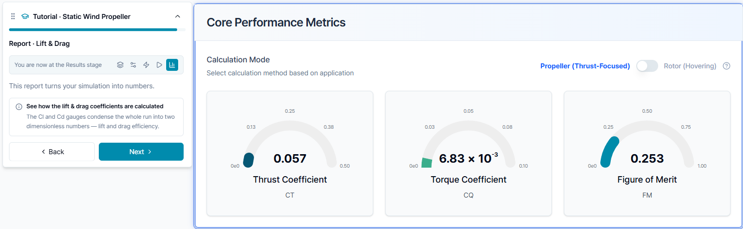
- Thrust is the axial force generated in still air.
- Torque indicates the motor torque required at the selected RPM.
- Power is the product of torque and angular speed.
- Figure of merit compares ideal and actual hovering efficiency.
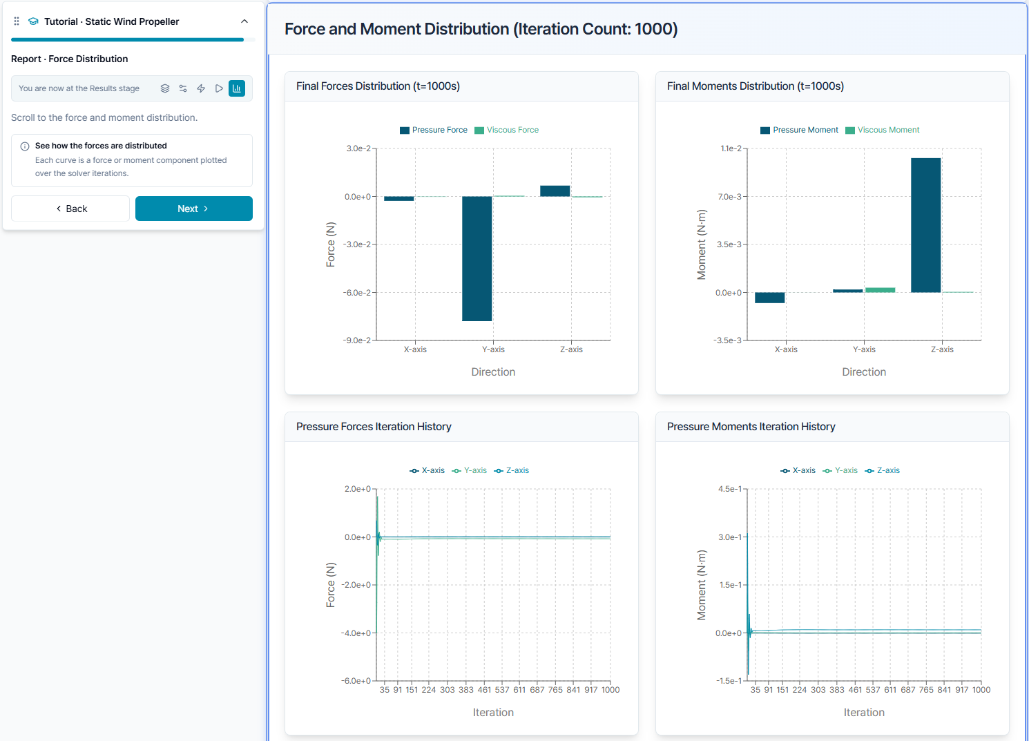
Use the force and moment charts to check which axis carries the thrust and whether pressure and viscous contributions stabilize across iterations.
Practical checks
- Static thrust means
Wind Speed = 0 m/s; RPM is still nonzero. - A sign error in the axis or rotation direction can produce negative thrust or an upstream wake.
- Compare propellers only at the same RPM, temperature, reference size, and mesh accuracy.
- Use the saved cut to explain the report, not as a replacement for the report itself.