Propeller: Flow Analysis
Target Propeller Information
- Diameter: 0.25 m
- MAC: 0.025 m
- Airfoil: NACA-0012
- RPM: 1000
- Inflow velocity: 4 m/s
Download Sample STEP File
Download the sample STEP file to follow along with this tutorial:
Step 1: Import CAD Geometry
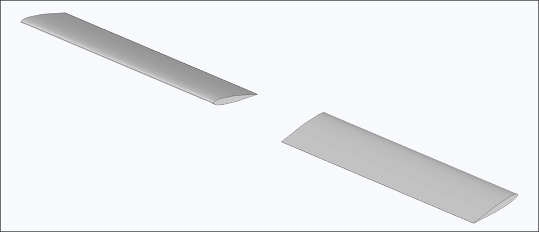
- Navigate to the Flow Analysis - Propeller module
- Click the Import CAD button
- Select the
NACA0012_Drone_rotor.stepfile - Verify that the import completed successfully
Important Notes:
- Geometry is directly reflected in the analysis without modification
- Ensure proper scale and units before importing
Step 2: Create Flow Domain
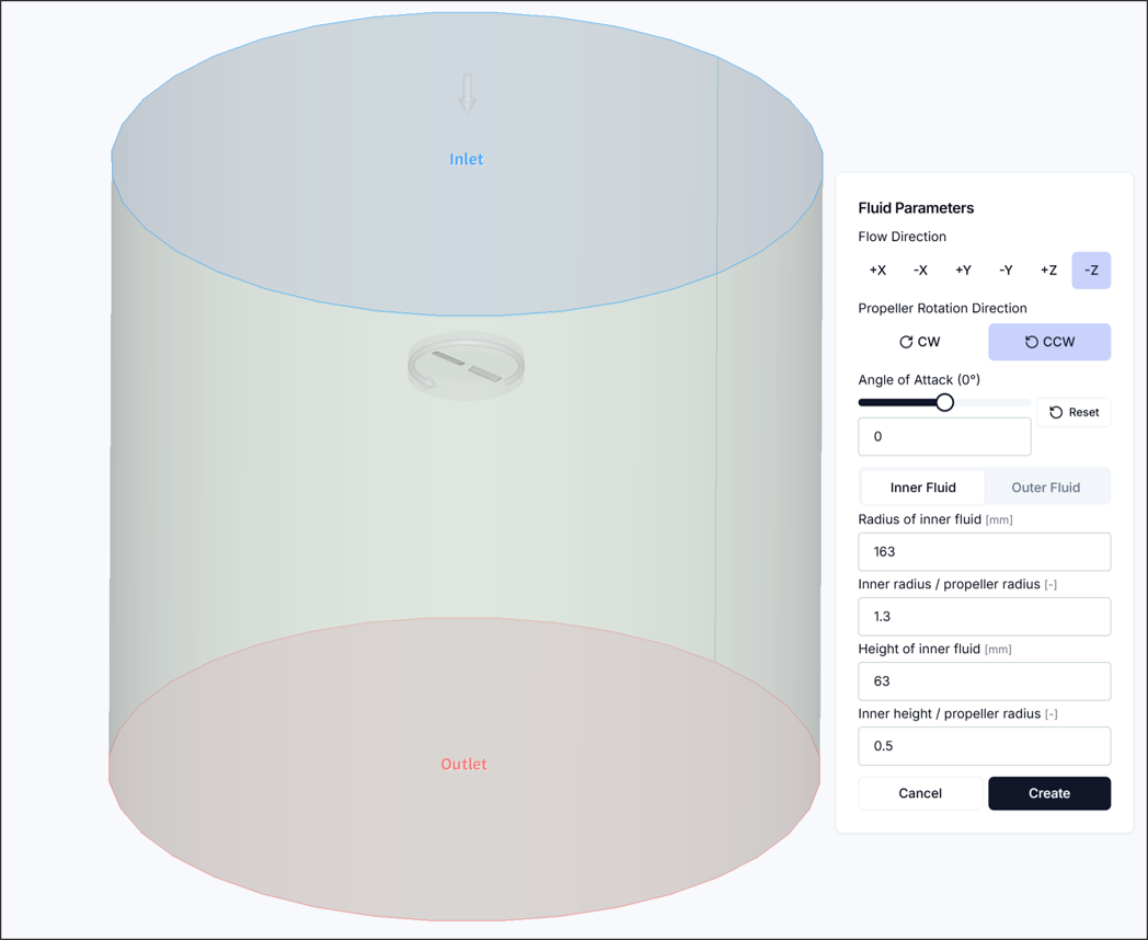
Set up the flow domain for analysis. This process defines the rotating flow region that spins with the propeller and the stationary external flow region surrounding it.
2.1. Flow Direction and Rotation Direction
- Flow Direction: Select one of 6 available flow directions
- Propeller Rotation Direction: Select the direction in which the propeller rotates
- Angle of Attack: Define the angle between the incoming flow direction and the normal of the propeller disk plane
Important Notes:
- The flow domain orientation must initially be set so that it is horizontal to the propeller rotation disk region
- The propeller rotation direction must be selected to match the actual rotation direction as observed from the geometry
2.2. Rotating Flow Region
Set up the flow domain that rotates with the propeller.
- Rotating Flow Radius: Define the diameter of the rotating flow region in the propeller blade direction
- Rotating Flow Height: Define the height of the rotating flow region in the propeller hub direction
Tips:
- The propeller diameter is automatically calculated from the CAD, so proportional values for the rotating flow radius or height can be used
- For typical propeller geometries, a rotating flow radius ratio of 1.1 – 1.3 and a rotating flow height ratio of 0.5 – 0.8 are recommended
2.3. External Flow Region
Set up the external flow domain required for the analysis.
- External Flow Radius: Define the diameter of the external flow domain in the propeller blade direction
- External Forward Flow Height: Define the length of the external flow domain in front of the propeller
- External Aft Flow Height: Define the length of the external flow domain behind the propeller
Tips:
- The propeller diameter is automatically calculated from the CAD, so proportional values for the external flow radius or height can be used
- For typical propeller geometries, an external flow radius ratio of 5 – 10, external forward flow height ratio of 5 – 8, and external aft flow height ratio of 10 – 30 are recommended
Once all values have been configured, click Create and verify that the flow domain geometry has been generated correctly as shown in the figure above.
Step 3: Configure Settings
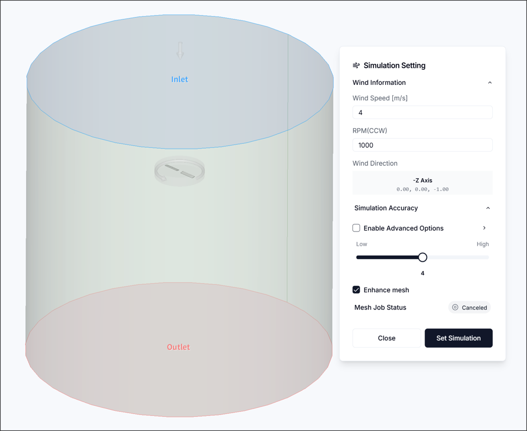
3.1. Flow Conditions
- Flow Velocity: 4 m/s
- RPM: 1000 RPM
3.2. Simulation Accuracy
- Set to 3
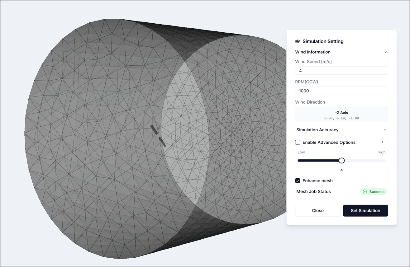
Once all values have been configured, click Configure Simulation and verify that the simulation settings have been applied and the mesh has been generated correctly.
Step 4: Run Simulation
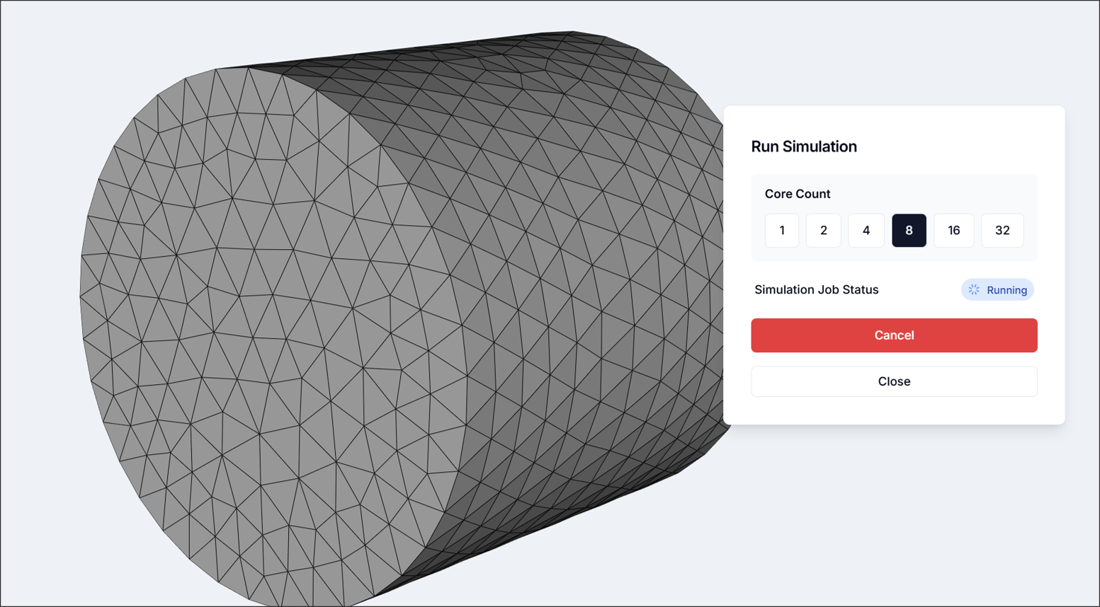
- 8 or more cores recommended
Run the simulation and wait until the analysis is complete.
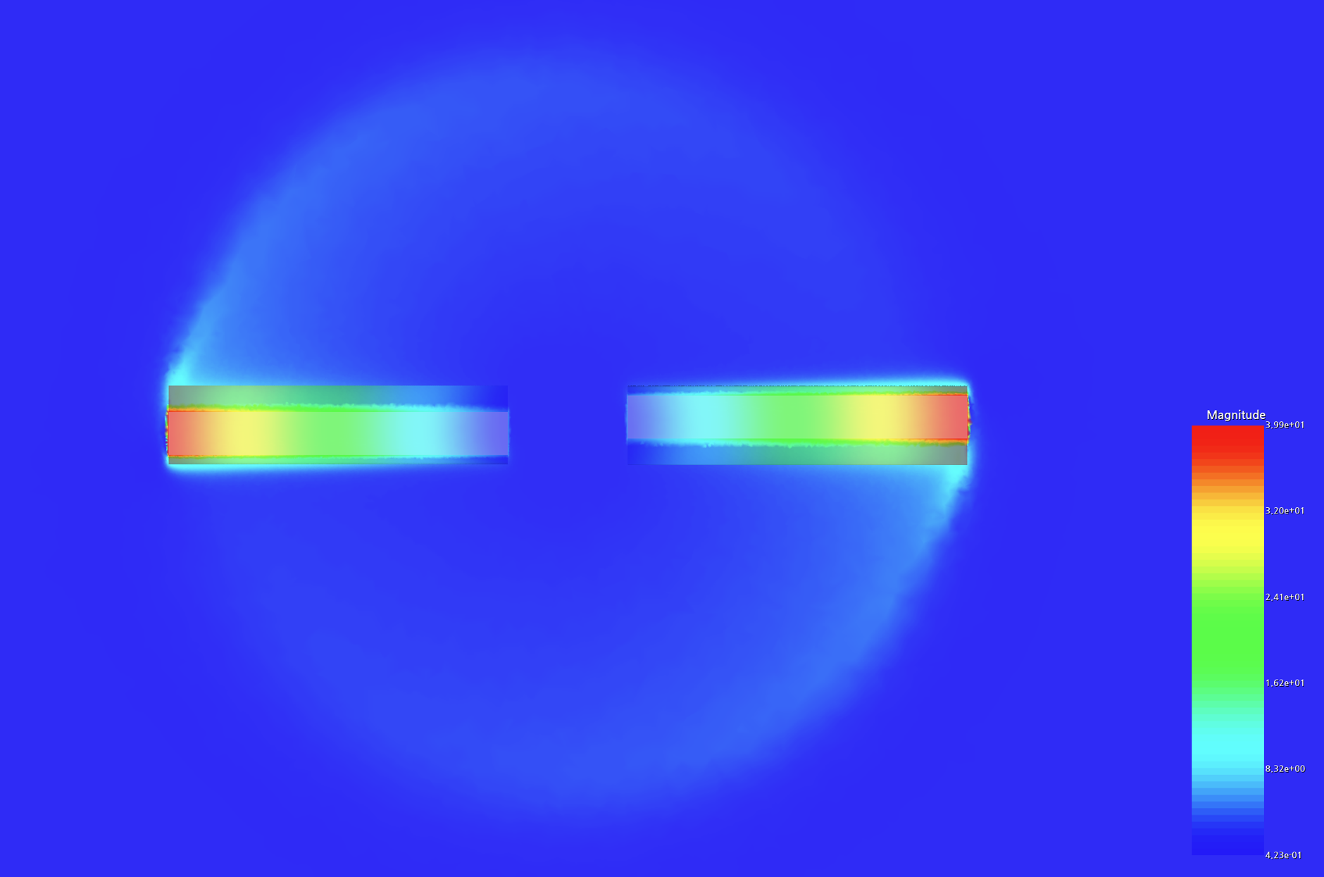
Step 5: Visualize Results
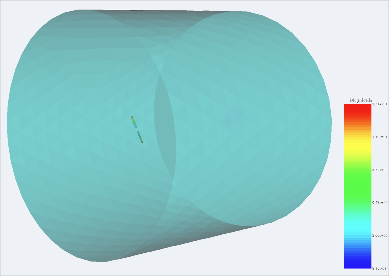
After the simulation is complete, you can review the physical quantities of interest (velocity, pressure, turbulence intensity, etc.) in the results window.
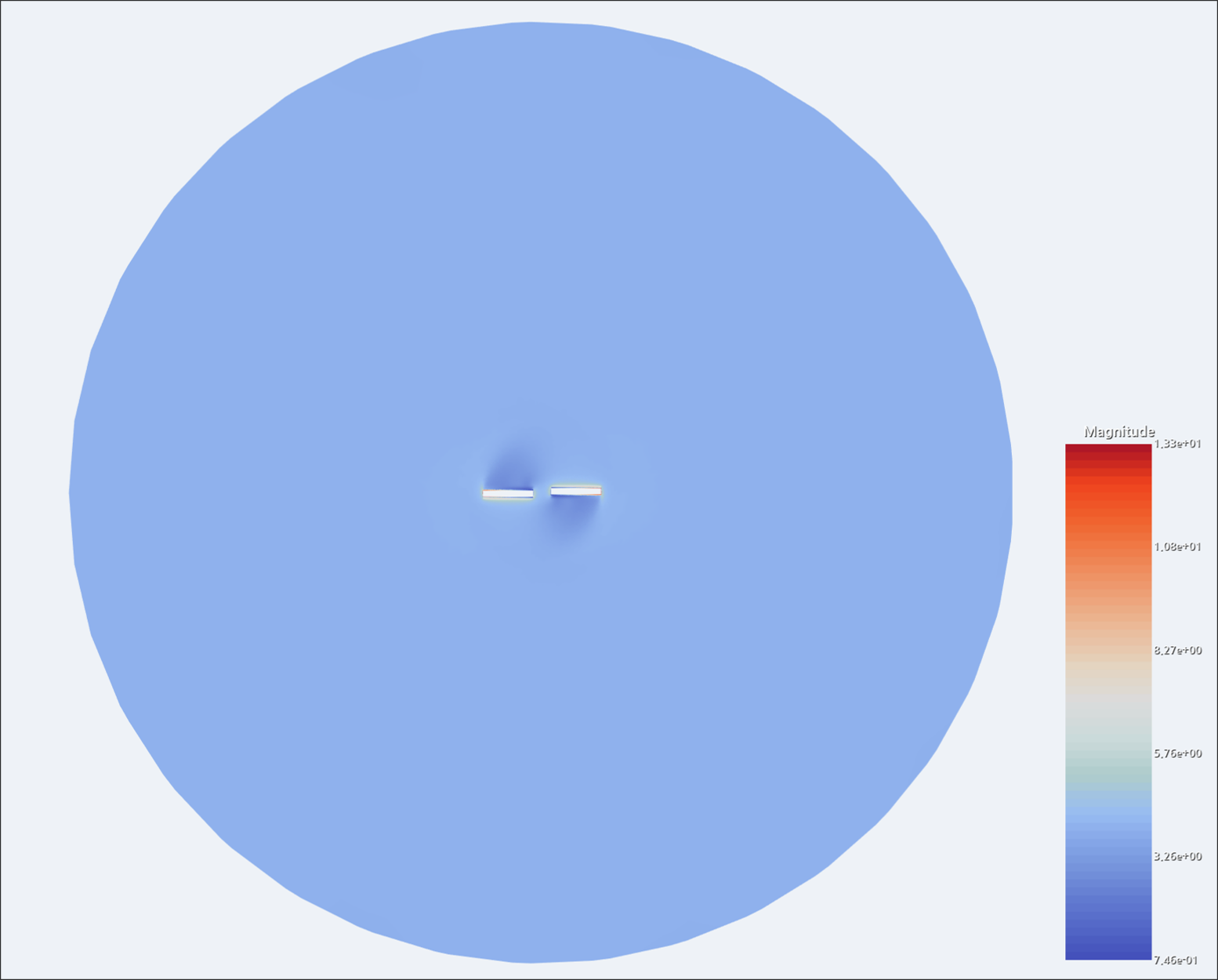
Tips:
- Viewing cross-sections is a convenient way to inspect physical phenomena in detail.
Step 6: Review Reports
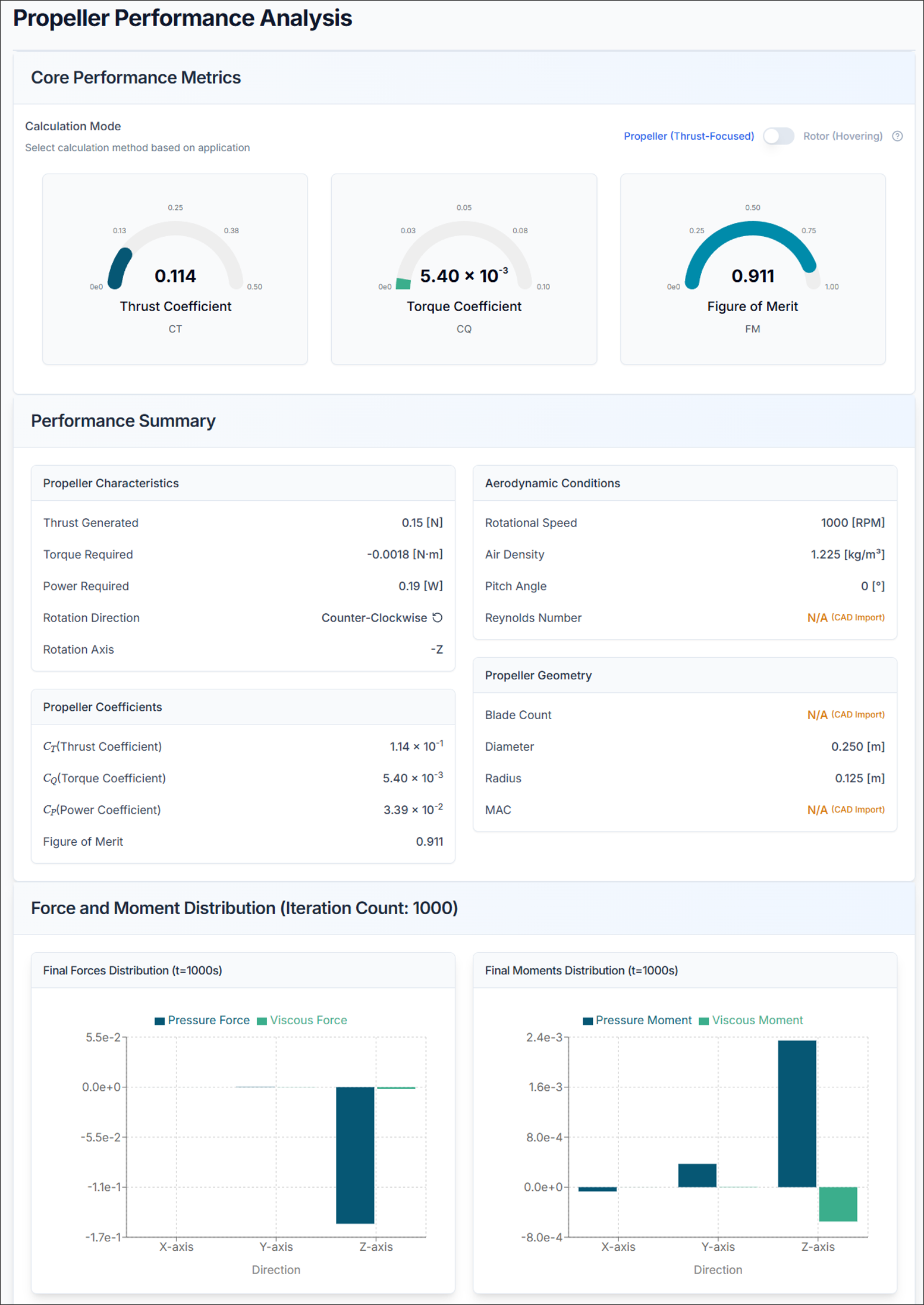
6.1. Propeller Performance
Thrust Coefficient (Ct)
- Higher Ct = more thrust per revolution
- Typical range: 0.08 - 0.15
Torque Coefficient (Cq)
- Represents power requirement
- Lower Cq = more efficient
Figure of Merit (FM)
- FM must be < 1.0
- Typical range: 0.6 - 0.85
- Higher FM = more efficient propeller
6.2. Forces and Moments
- Fx, Fy, Fz: Forces in x, y, z directions [N]
- Mx, My, Mz: Moments about x, y, z axes [N·m]
Analysis Tips:
- Total Thrust: Verify the result matches the expected lift requirements
- Moments: Should be balanced for stable flight
Propeller Design Tips and Troubleshooting
1) If Thrust is Insufficient
- Increase RPM
- Add more blades
- Increase blade chord length
- Increase twist angle
2) If Propeller Efficiency is Low
- Optimize blade twist distribution
- Reduce tip losses with winglets
- Improve airfoil selection
- Reduce blade interference
3) If Forces or Moments Are Problematic
- Check propeller geometry
- Adjust propeller position
- Review moment distribution
- Verify symmetric configuration
4) STEP Import Failure
- Solution: Verify that the STEP CAD geometry is appropriate for flow analysis
5) Analysis Takes Too Long
- Solution: Reconfigure the mesh count
6) Results Appear Unrealistic
- Solution: Verify that flow velocity + tip velocity < Mach 0.7, and review propeller configuration
7) Figure of Merit > 1.0
- Solution: Re-check input parameters, flow conditions, or RPM settings
Need Assistance or Have Questions?
Frequently Asked Questions: FAQ Link
Support Inquiries: support@everysim.io